Method and System for Object Reconstruction

a technology of object reconstruction and object data, applied in the field of method and system for object reconstruction, can solve the problems of low 3-d resolution, inability to provide real-time mapping of objects, and the 3d information obtained usually contains only relatively sparse samples, and achieves simple and inexpensive optical setup.

a technology of object reconstruction and object data, applied in the field of method and system for object reconstruction, can solve the problems of low 3-d resolution, inability to provide real-time mapping of objects, and the 3d information obtained usually contains only relatively sparse samples, and achieves simple and inexpensive optical setup.

US20100177164A1Active Publication Date: 2010-07-15APPLE INC

Image

  • Method and System for Object Reconstruction
  • Method and System for Object Reconstruction
  • Method and System for Object Reconstruction

Examples


Embodiment Construction

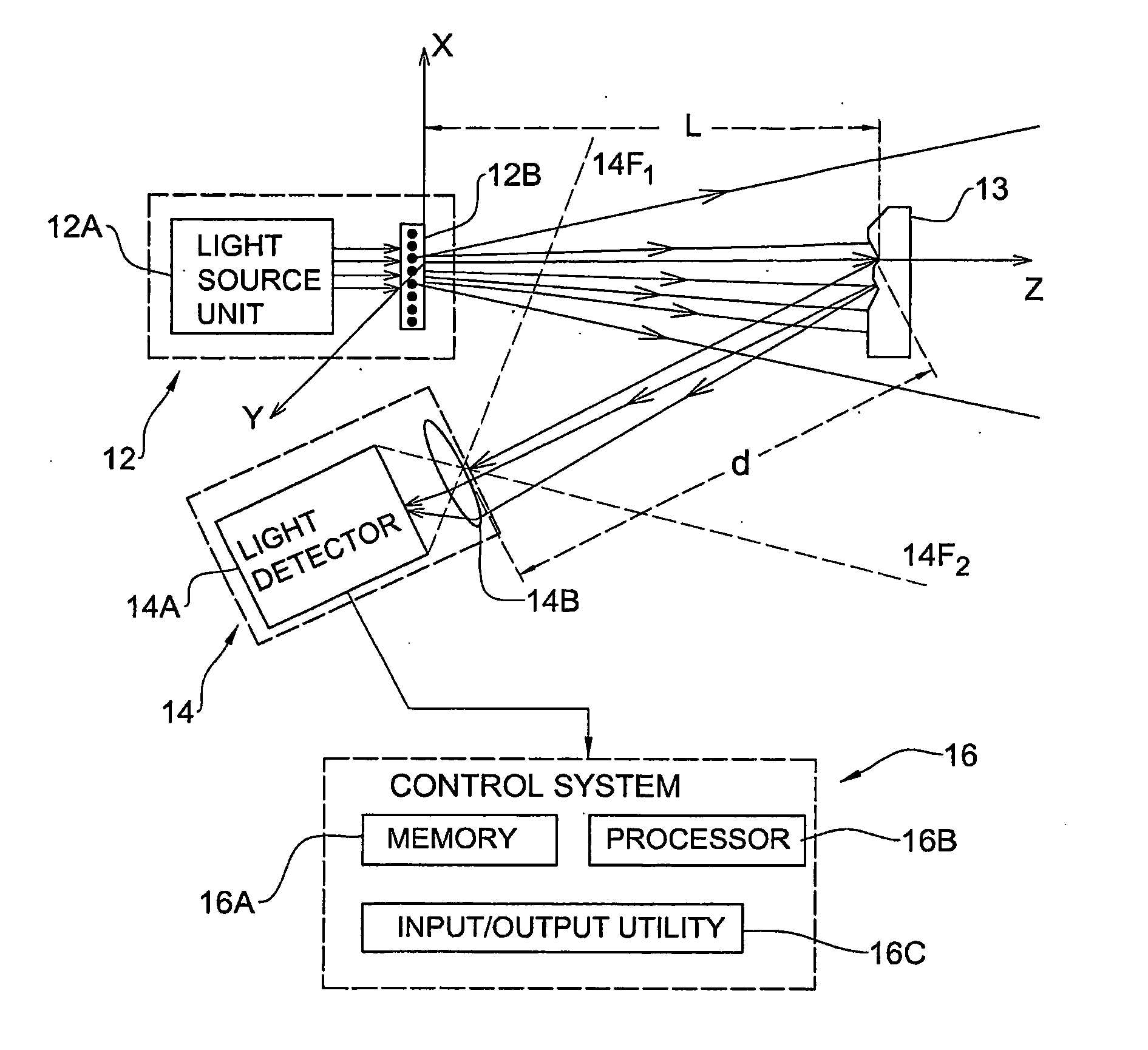
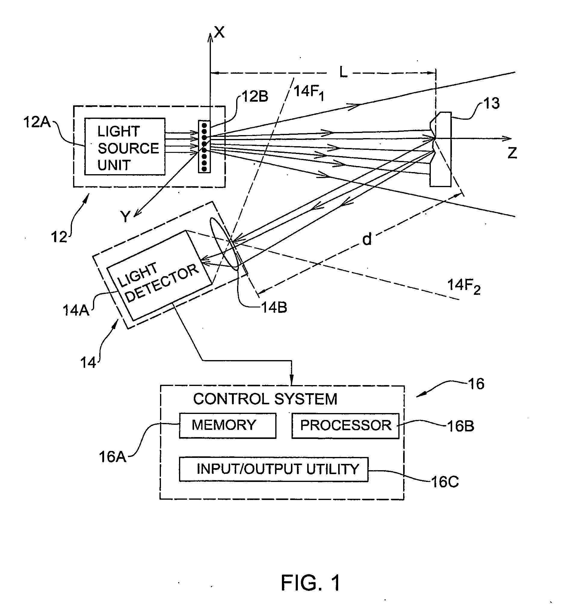
[0054]Referring to FIG. 1, there is schematically illustrated an example of a system 10 of the present invention for use in 3-D mapping of objects. System 10 is an optical mapping system including an illuminating unit 12 configured to project a random speckle pattern (preferably constant pattern) onto an object 13; and an imaging device 14.

[0055]Illuminating unit 12 includes a coherent light source 12A, and a generator 12B of a constant random speckle pattern accommodated in the optical path of illuminating light, preferably very close (e.g., up to a physical contact) to the light source output. Light source 12A may be constituted by a light emitting assembly (laser) and / or by a light guiding arrangement (e.g., optical fiber) associated with a remote light emitting assembly. Pattern generator 12B is a light diffuser, for example a ground glass.

[0056]Imaging device 14 includes alight detector 14A (a pixel matrix, e.g., CCD) equipped with an imaging lens arrangement 14B. The latter ma...


PUM


Abstract

A system and method are presented for use in the object reconstruction. The system comprises an illuminating unit, and an imaging unit (see FIG. 1). The illuminating unit comprises a coherent light source and a generator of a random speckle pattern accommodated in the optical path of illuminating light propagating from the light source towards an object, thereby projecting onto the object a coherent random speckle pattern. The imaging unit is configured for detecting a light response of an illuminated region and generating image data. The image data is indicative of the object with the projected speckles pattern and thus indicative of a shift of the pattern in the image of the object relative to a reference image of said pattern. This enables real-time reconstruction of a three-dimensional map of the object.

Description

REFERENCE TO CROSS-RELATED APPLICATIONS[0001]This application claims priority from U.S. provisional application No. 60 / 666,184, filed on Mar. 30, 2005, and from U.S. provisional application No. 60 / 724,903, filed on Oct. 11, 2005, herein incorporated by reference in its entirety.FIELD OF THE INVENTION[0002]This invention relates to a method and system for object reconstruction, enabling to extract highly resolved and real-time 3-D information.REFERENCES[0003]The following references are considered to be pertinent for the purpose of understanding the background of the present invention:[0004]1. S. Avidan and A. Shashua, “Trajectory triangulation: 3D reconstruction of moving points from amonocular image sequence,” PAMI, 22, 348-357 (2000).[0005]2. Y. G. Leclerc and A. F. Bobick, “The direct computation of height from shading,” CVPR, 552-558 (1991).[0006]3. R. Zhang and M. Shah, “Shape from intensity gradient,” SMC-A, 29, 318 (1999).[0007]4. R. Zhang and M. Shah, “Height recovery from i...

Claims


Application Information

Patent Timeline
15 Jul 2010
Publication
US20100177164A1
IPC
H04N13/02; H04N9/31; G06T17/05
CPC
G01B11/162; H04N13/02; G06T7/0057; G01B11/2513; G06T7/521; H04N13/20; H04N13/254; G06T17/00
Inventors
ZALEVSKY, ZEEV; SHPUNT, ALEXANDER