
Oil and Debris Separator

a technology of oil and debris separator and separator, which is applied in the direction of water cleaning, liquid displacement, separation process, etc., can solve the problems of reducing the efficiency of precipitation and affecting the quality of oil and other pollutants. , to achieve the effect of reducing production and shipping costs and reducing shipping and storage costs

Active Publication Date: 2010-07-22
DURAN LEE A +1
View PDF8 Cites 12 Cited by
  • Summary
  • Abstract
  • Description
  • Claims
  • Application Information

AI Technical Summary

Benefits of technology

[0028]It is another object of the present invention to provide a hood, and more specifically a novel hood wall, that efficiently facilitates the precipitation of particulates suspended in the wastewater flowing through the catch basin.
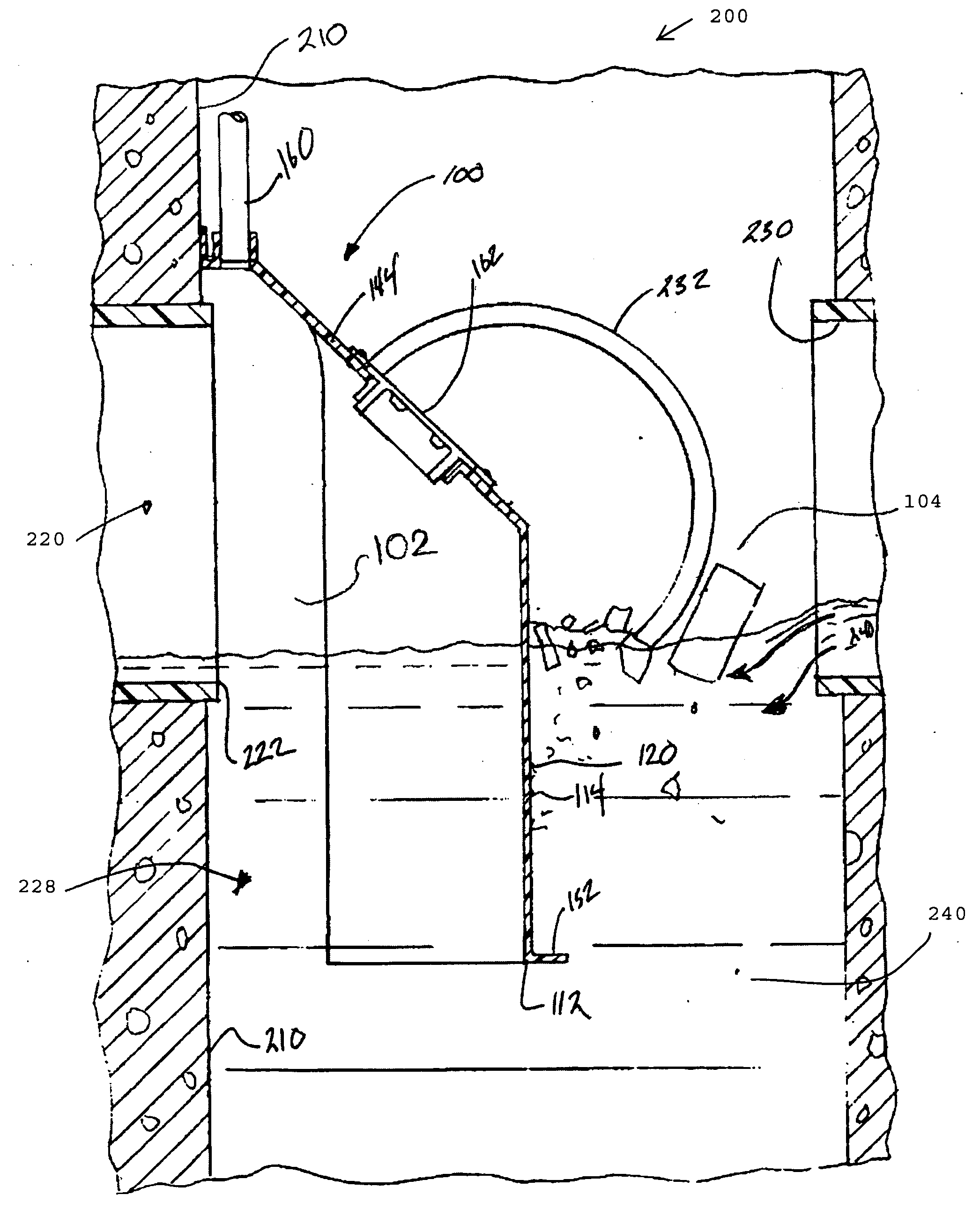
[0043]These and other objects of the present invention are achieved through an apparatus comprising a hood, wherein a front wall of the hood is formed in the shape of a prow that extends along an axis, thereby overcoming the problems of the prior art. More particularly, these and other objects of the present invention are achieved via an apparatus that extends along an axis, and has a wall shaped to partially sealingly fit around the outlet of an interior wall of catch basin so as to define at least a partially sealable compartment therewith that is open to the outlet and extends below the outlet so that waste materials floating on said water mixture outside of the compartment are prevented from entering said outlet, wherein the hood wall substantially forms a prow in a cross section plane being defined by a static waterline in said catch basin.

Problems solved by technology

However, catch basins are also often the entry point of pollutants from diffuse sources found in stormwater runoff.
As a result, polluted wastewater is often discharged untreated, directly into lakes, streams, and oceans.
A disadvantage of known hoods is that they do not efficiently facilitate precipitation of particulate suspended in the wastewater flowing through the catch basin.
Another disadvantage of known hoods is that they do not increase the distance of the flow path of wastewater flowing through the catch basin system, thereby facilitating precipitation of particulate suspended in the wastewater flowing through the catch basin.
Another disadvantage of known hoods is that they do not create multiple flow paths in a laminar fashion to increase the flow path of more rapidly accumulate on the surface of the wastewater outside the hood compartment.
With less surface area outside the hood compartment, oil and other pollutants that accumulate on the surface of the water and are more susceptible to being drawn under the hood and into the outlet pipe, especially as the level of pollutants increases, before they can be emptied from the catch basin by service personnel.
Another disadvantage of known hoods is that their ability to prevent oil and other pollutants from flowing under the bottom of the hood and into the outlet pipe decreases as the ratio of the area of the surface water inside the hood compartment to the area of the surface water outside the hood compartment increases.
This problem commonly occurs in catch basins having circular cross section in the horizontal plane.
Another disadvantage of known hoods and hood shapes is that they do not prevent ice from forming on the surface of the wastewater outside the hood compartment and proximate to the bottom of the hood.
Another disadvantage of known hoods is that they are susceptible to structure failure in high flow conditions, especially when used in catch basins having a circular cross section.
Known hoods are susceptible failure under these conditions because they the side of the hood wall are not perpendicular with the circular wall of the catch basin.
Another disadvantage of known hoods is they are not provided with an apparatus that prevents floatables and other debris inadvertently drawn under the bottom barrier of hood from entering the outlet. wastewater flowing through the catch basin and increase the settling ability of the drainage structure.
Another disadvantage of known hoods is that they do not induce a hydraulic wedge in wastewater that flows into the catch basin, thereby inducing two laminar counter-cyclic eddies, both creating a longer flow path than in known outlet hoods.
As wastewater is directed toward the known hood in the catch basin the known hood does not efficiently increase the length of the flow path of the wastewater flowing through the system.
Another disadvantage of known hoods is that they do not induce an increased laminar flow path in wastewater that enters the basin and flows toward the circular front wall of the hood.
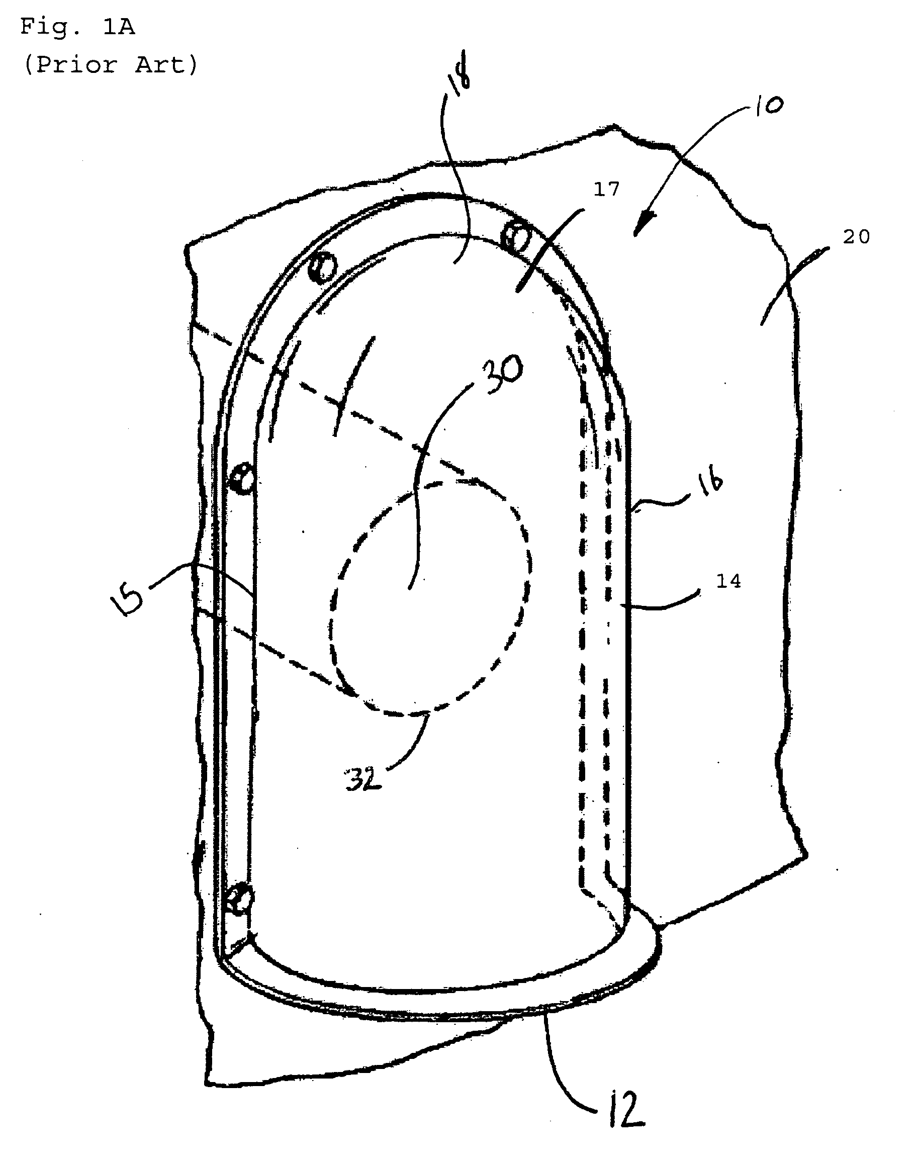
Another disadvantage of known hoods is that they are difficult to install in circular catch basins (circular in the horizontal plane), especially in catch basins having a relatively small diameter, because there is insufficient space for personnel to sealably mount the hood to the wall of the catch basin due to the curvature of the front of the hood and the curvature of the catch basin wall.
Another disadvantage of known hoods is that they cannot be used in a catch basin having a relatively small cross sectional area and relatively large outlet pipe.
Another disadvantage of known hoods is that their ability to prevent oil and debris from flowing under the bottom of the hood and into the outlet pipe decreases with a larger hood compartment (i.e. hood wall having a larger constant radius).
This in turn reduces the area on the water surface outside the hood compartment causing oil and pollutants to
Another disadvantage of known hoods is that they are increasingly difficult to mold from fiberglass or form from metal or plastic as the size of the hood increases.
As the dimensions of the hood increase the molding produces a less consistent shape, thereby increasing production costs, and limiting the strength of the outlet hood.

Method used


Image

  • Oil and Debris Separator
  • Oil and Debris Separator
  • Oil and Debris Separator

Examples


Embodiment Construction

[0064]Referring now to the drawings, wherein like reference numerals designate corresponding structure throughout the views.

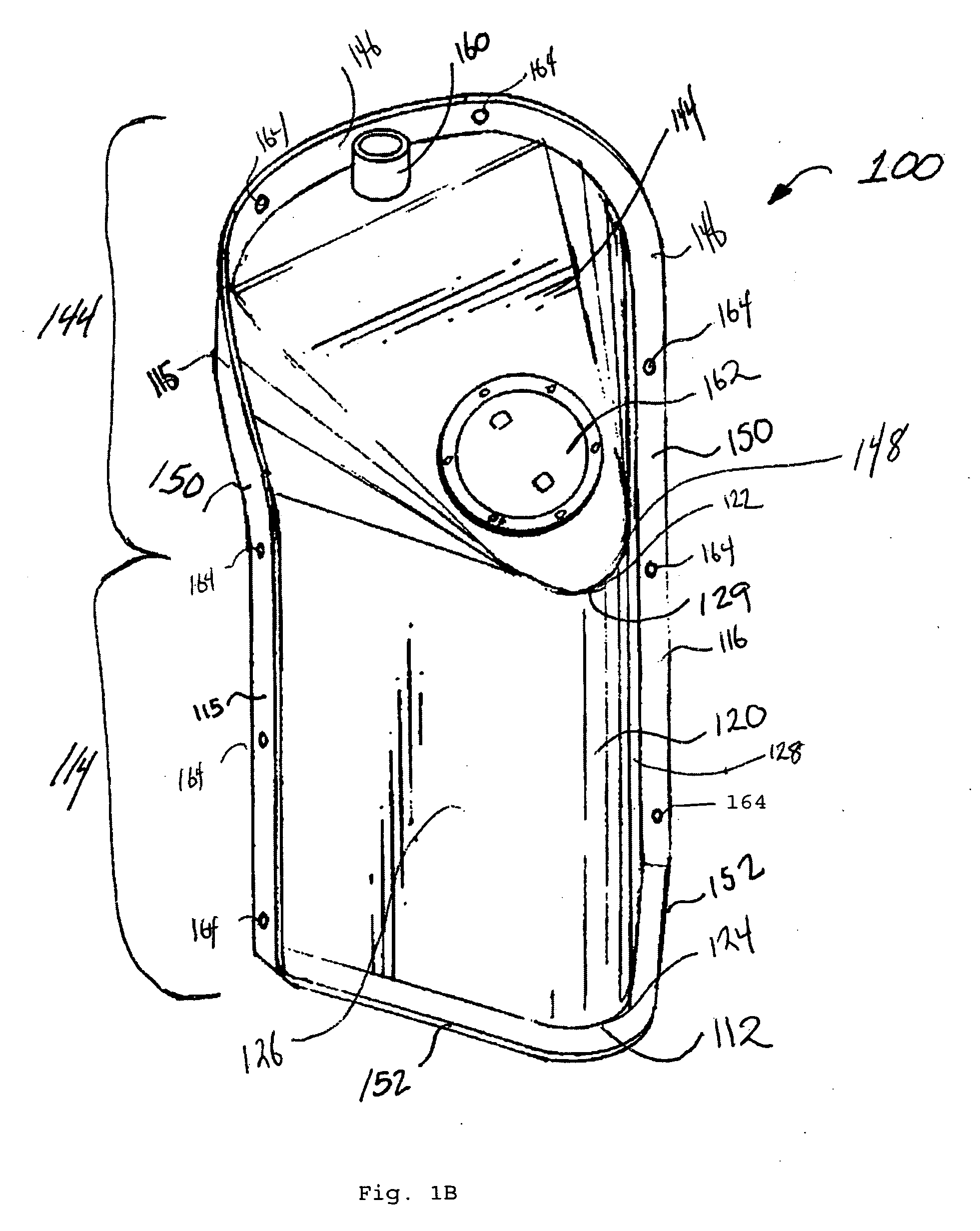
[0065]FIGS. 1B, 2, 3, 4, and 5 illustrate a novel hood 100 wherein the hood wall 114 forms a prow 120 or a wedge 120 that extends along an axis. The hood in FIGS. 1B, 2, 3, 4, and 5100 comprises a hood wall 114, and hood top 144. The hood wall 114 and the hood top 144 come together to form a continuous hood 100. The perimeter of the hood 100 has a flange 150. The flange 150 provides a surface to sealably mount the hood 100 to the catch basin wall 210. The hood 100 includes a vent 160 to equalize air pressure in hood compartment 102 with the ambient air in the catch basin 200 outside the hood compartment 104. The hood top 144 further includes an access port 162 for accessing the hood compartment 102 after installation. It should be understood that some embodiments of the present invention do not include a vent or vent pipe 160, and in some embodiments the air in...


PUM

PropertyMeasurementUnit
angleaaaaaaaaaa
specific gravityaaaaaaaaaa
differential specific gravityaaaaaaaaaa

Abstract

A hood for mounting over an outlet in a wall of a catch basin is disclosed. The hood includes a hood wall that forms a prow in a horizontal plane. The prow extends along an axis of the hood thereby achieving optimal flow conditions in the catch basin. In some embodiments the hood wall is shaped to be at least partially sealably mounted to the interior wall of a catch basin have a circular cross section in a horizontal plane. This novel hood shape facilitates installation of the hood in the circular catch basin, while also reducing the flow of oil and other pollutants into the outlet pipe in the circular catch basin. In some embodiments a perforated screed is also disclosed that surrounds the hood to aid in the capture of floatable pollutants.

Description

FIELD OF THE INVENTION[0001]The present invention relates to the field of wastewater management. More particularly the present invention relates to a low cost and effective apparatus for controlling and reducing the flow of pollutants and solids into an outlet of a catch basin.BACKGROUND OF THE INVENTION[0002]Stormwater runoff is characterized by the United States Environmental Protection Agency as one of the greatest remaining sources of water pollution in America. Thus, efforts to implement stormwater quality improvement regulations are accelerating across the United States, compelling municipalities and land developers to maximize the usefulness and effectiveness of stormwater infrastructure as never before.[0003]In urban, suburban, and commercial settings polluted stormwater, also referred to wastewater, is often collected in a catch basin, also referred to as a wastewater basin. In its simplest form, a catch basin functions to intercept surface water flows in order to prevent t...

Claims


Application Information

Patent Timeline
Patent Type & Authority Applications(United States)
IPC IPC(8): B01D21/24B01D17/02E03F5/14
CPCB01D17/0211B01D21/0006B01D21/0012B01D21/2444E03F5/16
Inventor DURAN, LEE A.MULLEN, III, THOMAS J.
Owner DURAN LEE A
Learn More