
Control system for a battery powered vehicle

a control system and battery technology, applied in the direction of anti-theft devices, engine starters, electric devices, etc., can solve the problems of limiting the range of vehicle travel, vehicle may be vulnerable to theft, and vulnerable to opportunist thieves, so as to achieve simple and cost-effective effects

Inactive Publication Date: 2010-07-22
INT TRUCK INTPROP LLC
View PDF51 Cites 20 Cited by
  • Summary
  • Abstract
  • Description
  • Claims
  • Application Information

AI Technical Summary

Benefits of technology

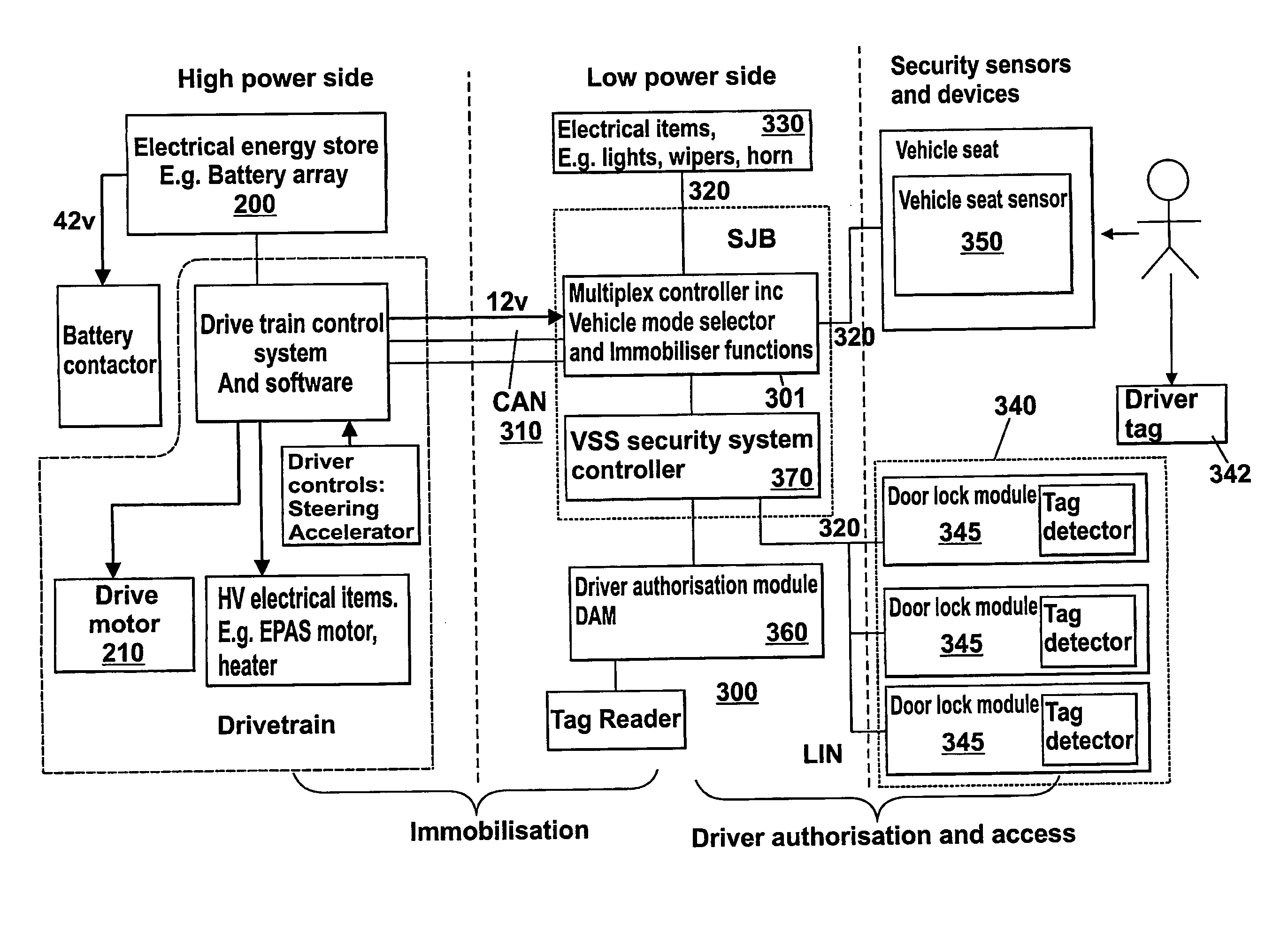
[0016]The provision of the control system which provides three different operating modes allows the vehicle electrical items to be gradually switched on and switch means, such as contactors, closed as the driver enters the vehicle and starts to operate the controls, yet when the driver leaves the vehicle keeps at least the contactors closed with the high power items switched off so that the electrical system can rapidly switch back to the third mode when a driver re-enters a vehicle yet minimal power is drawn. This ensures that there is no long delay when the vehicle is to be restarted. Additionally, repeated opening and closing of the contactors can cause wear due to arcing so keeping them closed if there is a good chance the vehicle may be started again is an advantage in terms of increased life of the contactors.
[0033]The vehicle control system may also be operable to place the vehicle in a fifth mode in which all electrical items are powered down. In this mode, for example, maintenance of the electrical system or removal of the battery can be performed without risk of electric shock.
[0037]For example, in one sub-mode the vehicle maximum speed may be set at its highest available level, and the torque available to the motor may be also set at its highest available level. In a second sub-mode the maximum available speed may be limited as well as the torque. In a third sub-mode the speed and torque may be limited still further. This allows different drivers with different experience levels to operate the vehicle safely, or allows operation of the vehicle in different conditions to be controlled. For example, one key may be issued which allows access to the first sub-mode if the vehicle journey covers fast roads such as motorways, with a second key being issued giving access to the third mode only if the vehicle is to be used in a built up urban area such as a city centre.
[0045]By providing a control system according to the second aspect the security of the vehicle against theft due to tampering with either the drive train or access control circuit is improved. Only if a drive train and access control unit which are correctly coded to one another is present will the vehicle immobiliser be deactivated. If a sub-unit that is taken from a different vehicle is used, for example one that is stolen from a different vehicle, it will not talk to the other sub unit and the vehicle can not be started.
[0049]This arrangement of coding a door module provides a simple and cost effective way of identifying different door modules on a vehicle. There is no need to provide different door modules which have codes written into their memory during manufacture—they can be coded during assembly by correct connection of the pins.

Problems solved by technology

To date a limitation of such vehicles has been the amount of energy that can be stored in the electric power source that in turn limits the range that the vehicle can travel between recharging.
A further problem appreciated by the applicant is that the security of a delivery vehicle, and to a lesser extent other vehicle types, is paramount as the driver is continually getting in and out of the vehicle.
It is all too easy for the driver to forget, or choose not, to turn off the vehicle when making a delivery, which makes it vulnerable to an opportunist thief.
In any event, the vehicle may be vulnerable to theft.
Whilst such immobilisers work well on petrol / diesel cars, they do not function well on electric vehicles due to the relatively long period of time it takes the battery and other electrical systems to move from a powered down state to a state in which the vehicle is ready to drive.
This time delay may prove irritating to a delivery driver who is repeatedly getting in and out of the vehicle if the immobiliser activates each time.
Leaving things powered up all the time, on the other hand, will simply drain the battery reducing the range of the vehicle and leave it vulnerable to theft.
Also, repeated opening and closing of the contactors can cause premature wear due to arcing and the like.

Method used


Image

  • Control system for a battery powered vehicle
  • Control system for a battery powered vehicle
  • Control system for a battery powered vehicle

Examples


Embodiment Construction

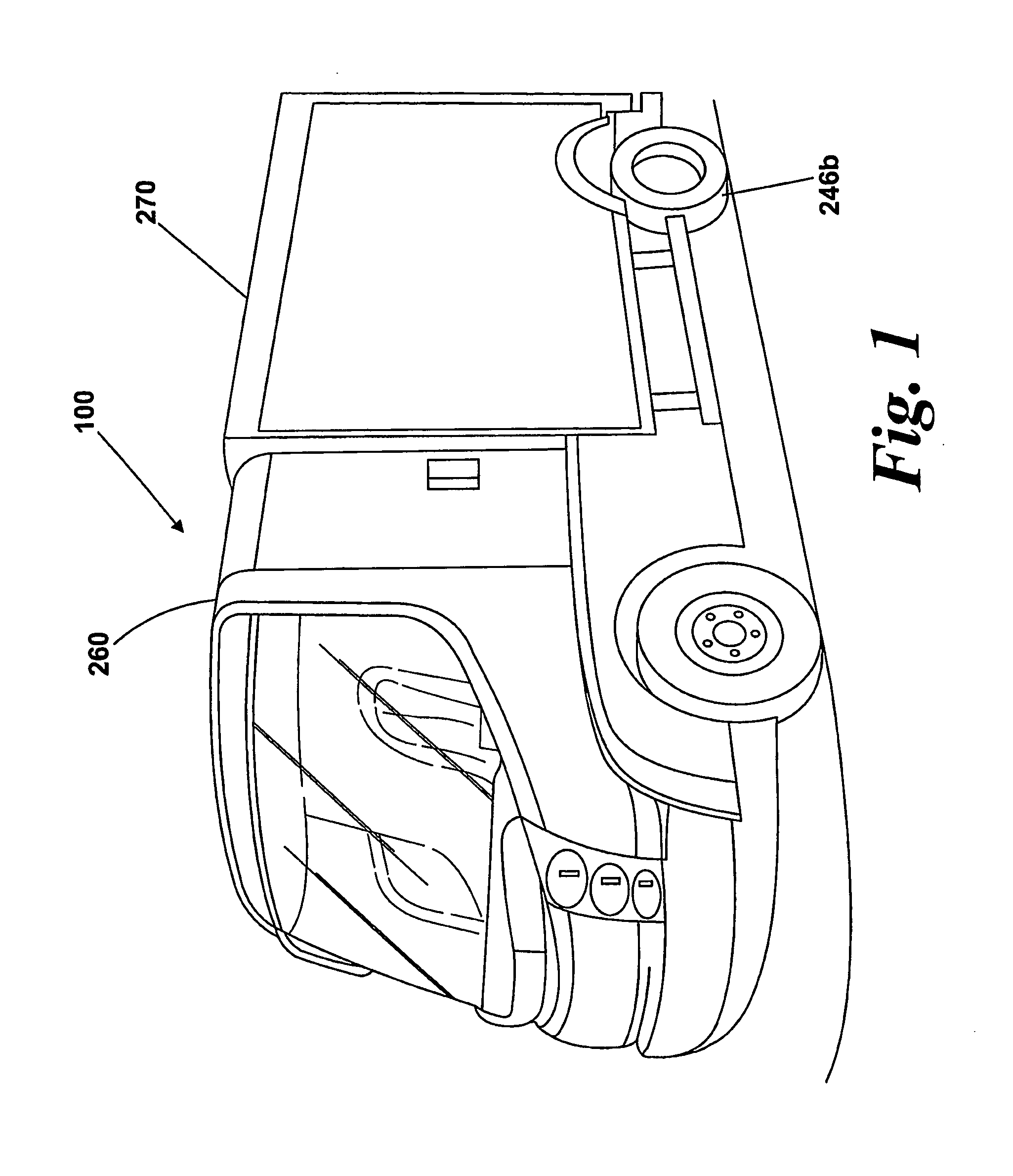
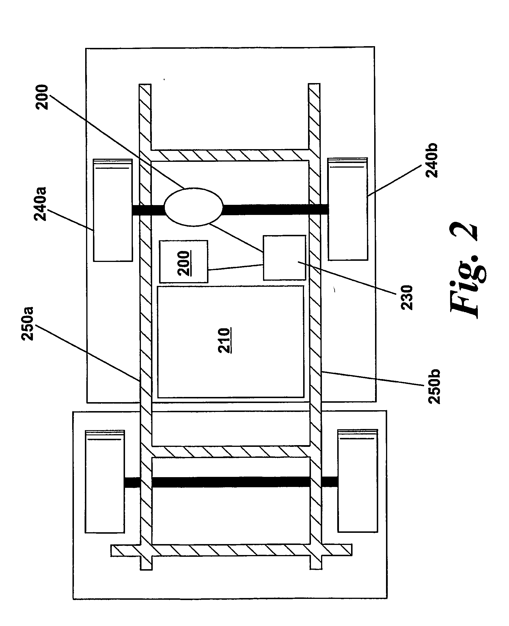
[0069]FIG. 1 shows an electric vehicle 100. The vehicle in this example is a specialist delivery vehicle, but through a simple change to the vehicle body it could be a box van or minibus or any other commercial or domestic use vehicle. At its heart is an electric drive train including an electric motor 200 which is supplied with power from a battery assembly 210. This is shown in FIG. 2 of the drawings which shows schematically the vehicle viewed from below. The motor drives a rear axle 229 of the vehicle 100 through a gearbox 230. The rear axle connects to two rear wheels of the vehicle 240a, 240b.

[0070]The battery assembly 210 comprises a self contained unit that comprises battery cells, battery control circuitry for regulating the battery charge and voltage, and a set of contactors which selectively connect the batteries to the units output terminals or isolate them. The contactors typically comprise relays and as such consume power to hold the contacts closed. The battery in th...


PUM


Abstract

A control system for a battery powered vehicle of the kind which is provided with an electric power source and at least one switch means, such as a contactor, which is operable to connect the output of the power source to a high power electrical item fitted to the vehicle, such as an electric drive motor, in which the control system is operable to set the vehicle in one of at least 3 different operating modes comprising a first mode in which the vehicle is immobilised and the contactor is held in an open position to isolate the battery from the electrical item, a second mode in which the vehicle is not immobilised and the contactor is held in a closed position to connect the battery to the electrical item, and a third mode in which the vehicle is immobilised but the contactor remains in an closed position to connect the battery to the electrical item.

Description

FIELD OF THE INVENTION[0001]This invention relates to a control system for a vehicle. It also relates to a security system for a vehicle, which can, optionally be combined with the control system. In particular it relates to electric vehicles and to control and security systems that may be fitted to such vehicles. It will be appreciated that the security systems, in particular, could be fitted to other non-electric vehicles such as those that use an internal combustion engine or so called hybrid internal combustion / electric vehicles.BACKGROUND OF THE INVENTION[0002]As more and more consumers and businesses become mindful of the effect of vehicle emissions on the environment there has been a drive towards the development of electric powered vehicles, which use electrical power sources and electric motors as the heart of their drive train. A battery-powered vehicle will emit no harmful carbon dioxide emissions and can be charged quickly and easily by connecting it to a mains power sup...

Claims


Application Information

Patent Timeline
IPC IPC(8): B60L1/00B60R25/04B60R25/045B60R25/24
CPCB60R25/24Y02T90/16B60L2200/36B60L2270/36B60L2200/26F02N11/0811B60R25/045B60L3/04F02N2200/106B60R25/04F02N11/10Y02T10/70B60L50/50
Inventor CUNNINGHAM, IAINSHEEHAN, CHRIS
Owner INT TRUCK INTPROP LLC
Learn More