System and method for ammonia synthesis

a technology of ammonia and synthesis method, which is applied in the field of ammonia synthesis, can solve the problems of high pressure and temperature, low reaction efficiency, increased operational and capital costs, etc., and achieves the effects of improving the function of nano-size catalyst particles, reducing the cost of operation and capital costs, and maintaining durability

Inactive Publication Date: 2010-07-22
BRICOLEUR PARTNERS LP
View PDF23 Cites 12 Cited by
  • Summary
  • Abstract
  • Description
  • Claims
  • Application Information

AI Technical Summary

Benefits of technology

[0015]The invention described herein comprises the synthesis of ammonia by providing core-shell iron / iron oxide nanoparticles on ferrous catalysts to improve catalytic activity while maintaining durability. In various embodiments herein, systems and methods for the synthesis of ammonia are disclosed that are capable of being used in both traditional and new ammonia reactor bed designs. The function of the nano-size catalyst particles is improved by dispersing or separating the particles using a support material, thereby reducing or eliminating sintering of adjacent particles. The result are systems and methods that can operate at much lower pressures than the Haber-Bosch process and that can maintain catalysis efficiency over time.

Problems solved by technology

However, in practice, both high pressures and temperatures are used due to a sluggish reaction rate.
Due to overall low reaction efficiency when hydrogen and nitrogen are first passed over the catalyst bed, most ammonia production plants utilize multiple adiabatically heated catalyst beds with cooling between beds, typically with axial or radial flow.
High pressure favors the adsorption process as well, but at a cost of increased operational and capital costs.
Nevertheless, due in part to high pressures used in the process, ammonia production requires reactors with heavily-reinforced walls, piping and fittings, as well as a series of powerful compressors, all with high capital cost.
In addition, generation of those high pressures during plant operation requires a large expenditure in energy.
Use of this catalyst allowed the reactor pressure to be reduced, but the high cost of the precious metal ruthenium catalyst and the sensitivity of the catalyst to impurities in the hydrogen feed stock have prevented widespread use for ammonia synthesis.
Other catalysts being studied include cobalt doped with ruthenium, but few encouraging results have been exhibited to date.
Suggestions of reducing the processing pressures have been made, but have not been achieved economically.
U.S. Pat. No. 3,653,831 describes the addition of platinum to improve reaction efficiency, however given the expense of platinum this may not be feasible at large scales.
Retrofit and reconstruction of these plants could be costly should there be a need to change design based on catalyst properties, such as space velocity.
Non-ferrous catalysts in the above referenced prior art do not overcome all of these constraints because 1) catalyst cost increases more than catalyst efficiency, 2) the catalyst may not have the same properties that allow for seamless operation in existing ammonia production plants, or 3) the catalyst may have high activity but do not meet long term durability requirements.

Method used


Image

  • System and method for ammonia synthesis
  • System and method for ammonia synthesis
  • System and method for ammonia synthesis

Examples


example 1

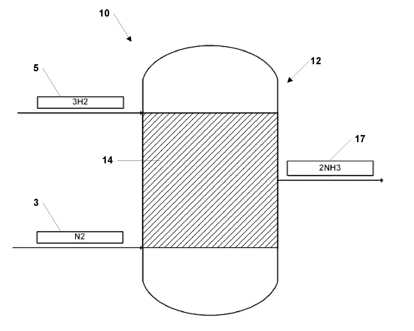
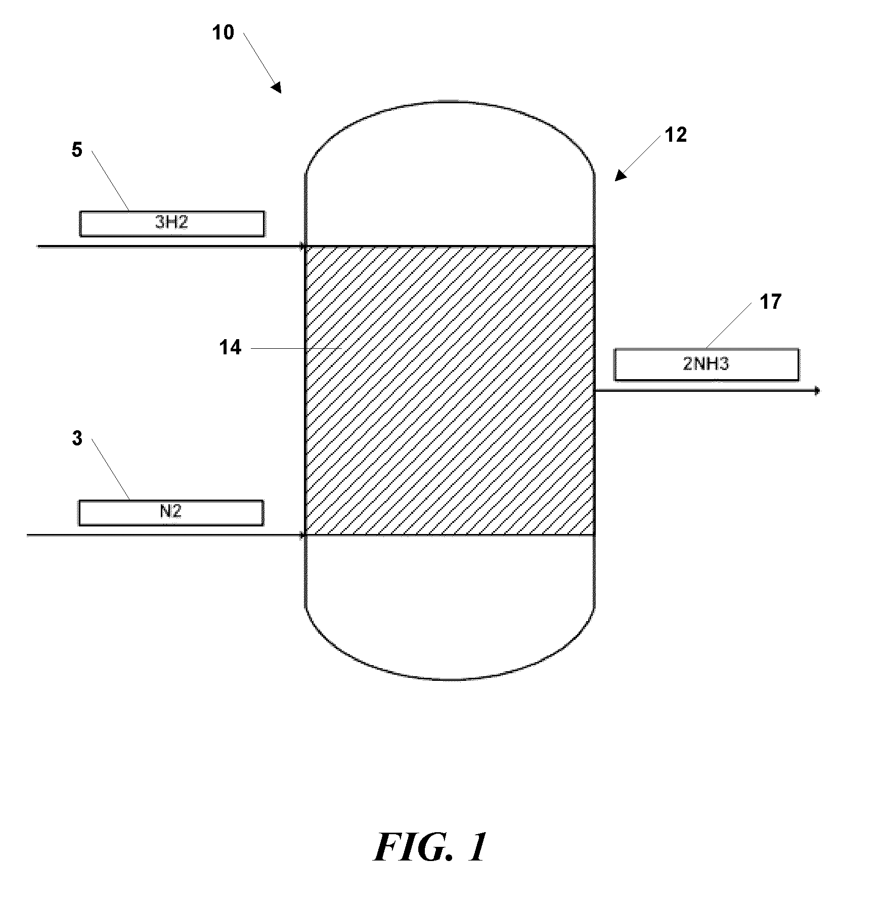
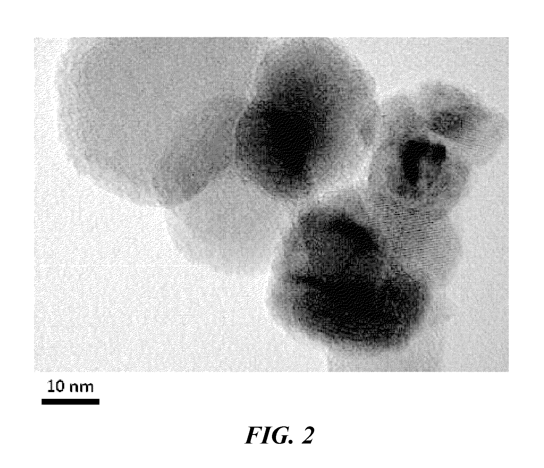
[0039]Synthesis of NH3 was performed over a bed of nano-sized ferrous catalyst particles, manufactured using the vapor condensation process described in U.S. Pat. No. 7,282,167 to Carpenter, and supported with silicon nitride tubes. The nano-sized ferrous catalyst particles comprised an oxide coating between about 0.5 and 1.5 nanometer thickness. The particles had average diameters from 15 to 25 nanometers.

[0040]The supported nano-sized ferrous catalyst particles were piled in a packed bed configuration within a plug flow reactor system. Hydrogen and nitrogen gases were introduced into to plug flow reactor system as described above at pressures between about 10 atm and 20 atm and a temperature of about 450° C.

[0041]Ammonia was detected and alkalinity tests conducted with pH paper yielded a pH of 11, typical of ammoniacal solutions in water. The experiment established the production of ammonia from hydrogen and nitrogen at vastly reduced pressures, as compared to industrial processes...

example 2

[0042]Synthesis of ammonia was performed over a bed of nano-sized ferrous catalyst particles, manufactured using the vapor condensation process described in U.S. Pat. No. 7,282,167 to Carpenter, and supported on SG9801R promoted iron from BASE. The nano-sized ferrous catalyst particles comprised an oxide coating between about 0.5 and 1.5 nanometer thickness rendering them air safe for mixing. The particles had an average diameter from 15 to 30 nanometers. The nano-sized iron and iron support particles were blended for 2 minutes at 20G with an acoustic mixer to distribute the nano-sized particles onto the support iron particles.

[0043]Supported nano-sized ferrous catalyst particles were piled in a packed bed configuration within a plug flow reactor system. The supported nano-sized iron particles were reduced in a stream of hydrogen gas at 300° C. Hydrogen and nitrogen gasses were introduced into the plug flow reactor system as described above at pressures between about 5 atm and 10 at...


PUM

PropertyMeasurementUnit
pressureaaaaaaaaaa
energyaaaaaaaaaa
adsorptionaaaaaaaaaa

Abstract

Systems and methods are disclosed herein for synthesizing ammonia using nano-size metal or metal alloy catalyst particles. Hydrogen and nitrogen gases are passed through a system comprising, for example, a bed of magnetite supporting nano-size iron or iron alloy catalyst particles having an optional oxide layer that forms the catalyst.

Description

RELATED APPLICATION[0001]This application is a continuation-in-part of U.S. patent application Ser. No. 12 / 418,356, filed Apr. 3, 2009, which is a continuation-in-part of U.S. patent application Ser. No. 12 / 266,477, filed on Nov. 6, 2008, which claims priority from Provisional Application No. 60 / 985,855, filed on Nov. 6, 2007, the entire contents of each of which are hereby incorporated by this express reference.BACKGROUND[0002]1. Technical Field[0003]The disclosure relates generally to the synthesis of useful chemical byproducts and, more specifically, to the synthesis of ammonia using nano-size metal catalyst particles.[0004]2. Related Art[0005]Ammonia synthesis is an important industrial process. Ammonia is produced in huge quantities worldwide, for use in the fertilizer industry, as a precursor for nitric acid and nitrates for the explosives industry, and as a raw material for various industrial chemicals.[0006]Despite an energy production cost of about 35 to 50 GJ per ton of am...

Claims


Application Information

Patent Timeline
Patent Type & Authority Applications(United States)
IPC IPC(8): C01C1/04C01C1/02
CPCB01J23/745B01J35/0013C01C1/0411B82Y40/00Y02P20/52
Inventor CARPENTER, R. DOUGLASMALONEY, KEVIN
Owner BRICOLEUR PARTNERS LP
Why Eureka
Try Eureka