Honeycomb catalytic article

a catalytic article and honeycomb technology, applied in the field of honeycomb catalytic article, can solve the problems of hysteresis with respect to the total amount of pm deposition, rapid rise in pressure loss, and high cost, and achieves the effects of reducing the amount of pm deposited, reducing the amount of pm oxidation, and increasing porosity

Active Publication Date: 2010-07-22
NGK INSULATORS LTD
View PDF12 Cites 41 Cited by
  • Summary
  • Abstract
  • Description
  • Claims
  • Application Information

AI Technical Summary

Benefits of technology

[0011]The present invention has been made by repeated studies in order to solve such problems and aims to provide a DPF where, in addition to good PM trapping efficiency and small pressure loss upon PM deposition, no rapid rise of pressure loss right after the start of trapping PM (initial stage of PM deposition) is caused (solution to the aforementioned problems (a) and (f)), the relation between PM deposition amount and pressure loss has no hysteresis characteristic (solution to the aforementioned problem (b)), pressure loss in an early stage having no PM deposition is suppressed low (solution to the aforementioned problem (c)), the surface layer is hardly peeled off (solution to the aforementioned problem (d)), and the whole catalyst is effectively used for the PM oxidation treatment (solution to the aforementioned problem (e)).
[0027]A honeycomb catalytic article of the present invention exhibits the following effects by being used as a DPF.
[0029]Since, in a preferable mode of a honeycomb catalytic article of the present invention, the surface layer has a peak pore size of 0.3 μm or more and below 10 μm and a porosity of 40% or more and below 95%, it is superior to the case without such limitations from the viewpoints of maintaining good PM trapping efficiency, inhibition of rapid rise of pressure loss right after the start of trapping PM, reducing pressure loss upon PM deposition, and durability of the surface layer.
[0030]Since, in a preferable mode of a honeycomb catalytic article of the present invention, the thickness L1 of the surface layer is 3% or more and below 15% of the thickness L2 of the partition walls, it is particularly excellent in that pressure loss upon PM deposition and in an initial state where no PM deposits can be suppressed to be low.
[0031]Since, in a preferable mode of a honeycomb catalytic article of the present invention, the partition wall matrix contains at least one kind selected from the group consisting of cordierite, Si-bonded SiC, recrystallized SiC, aluminum titanate, mullite, silicon nitride, and sialon as the main component, it is excellent in thermal stability under high temperature conditions.
[0033]Since, in a preferable mode of a honeycomb catalytic article of the present invention, a (an oxidation) catalyst containing one of or both platinum and palladium is loaded on the surface layer, oxidation of PM deposited can be accelerated. Specifically, since the surface layer has higher porosity than that of the partition wall matrix to have a larger surface area, by loading an oxidation catalyst on the surface area, it becomes possible to raise a contact frequency between the catalyst and the PM in comparison with the conventional case of loading a catalyst in pores of the partition wall matrix to accelerate oxidation of the PM deposited more, and, as a result, the PM deposition amount can be maintained to be low, thereby reducing pressure loss upon PM deposition.

Problems solved by technology

However, a DPF where such a honeycomb filter is applied has the following problems to be solved.
Therefore, right after the start of trapping PM, substantial porosity of the partition walls may fall to speed up the flow rate of exhaust gas passing through the partition walls, and thereby pressure loss may rapidly rise.
Such rapid rise in pressure loss right after the start of trapping PM is not preferable because it causes deterioration in engine performance.
However, in a DPF having such a conventional partition wall pore structure, since only PM deposited in pores is naturally combusted, pressure loss has hysteresis with respect to the whole PM deposition amount, and it is impossible to estimate the PM amount with high accuracy on the basis of pressure loss.
However, it is not desirable to reduce the pore size of the partition walls and increase the thickness of the partition walls because it causes increase of pressure loss of the partition walls themselves before PM deposition to deteriorate engine performance.
However, conventionally, there is a case that the surface layer is peeled to deteriorate filtration accuracy.
However, since there are many cases that the PM (fine particle substance) deposits more on the inlet side of the partition walls without reaching the vicinity of the surface on the outlet side.
Therefore, a catalyst in the partition walls cannot be used effectively.
As a result, deteriorations in engine output and fuel cost performance occur.

Method used


Image

  • Honeycomb catalytic article
  • Honeycomb catalytic article
  • Honeycomb catalytic article

Examples


example

[0081]Hereinbelow, the present invention will be described more specifically by Examples. However, the present invention is by no means limited to these Examples.

examples 1 to 15

, Comparative Examples 1 to 4

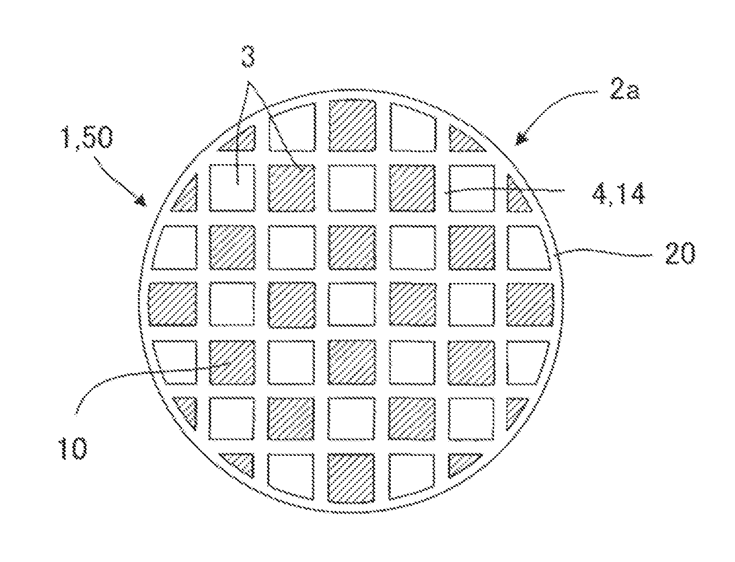
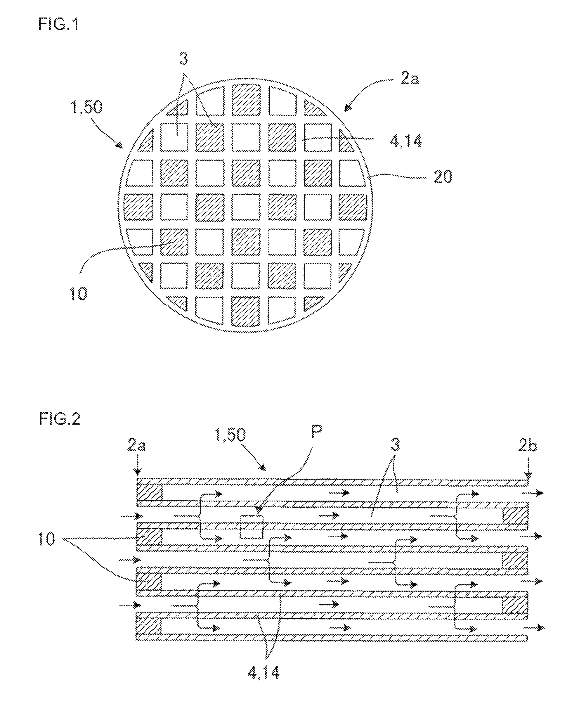
[0082][Manufacture of honeycomb formed article] As the cordierite forming raw material, alumina, aluminum hydroxide, kaolin, talc, and silica were used; and, to 100 parts by mass of the cordierite forming raw material were added 13 parts by mass of a pore former, 35 parts by mass of a dispersion medium, 6 parts by mass of an organic binder, and 0.5 parts by mass of a dispersant, followed by mixing and kneading to them prepare kneaded clay. Water was used as the dispersion medium, coke having an average particle size of 10 μm was used as the pore former, hydroxypropylmethyl cellulose was used as the organic binder, and ethylene glycol was used as the dispersant. Then, the kneaded clay was subjected to extrusion forming using a predetermined die to obtain a honeycomb formed article having a quadrangle cell shape and a circular columnar (circular cylindrical) whole shape.

[Manufacture of plugged honeycomb structure] After the honeycomb formed article was sub...


PUM

PropertyMeasurementUnit
porosityaaaaaaaaaa
porosityaaaaaaaaaa
pore sizeaaaaaaaaaa

Abstract

There is provided a honeycomb structure where a catalyst is loaded on surfaces of inner pores of the surface layer and on a surface of the surface layer; a relation between a catalyst area proportion A of the catalyst to a gap area proportion B of a gap in a cross-section of the surface layer on the inlet side is 1%<A / B<90%; and a relation between an average catalyst area proportion, A1, from the surface to a point having a depth of one third of the thickness of the surface layer including the surface of the surface layer on the inlet side and a catalyst area proportion A2 in a central portion of the surface layer is A1 / A2>1.5.

Description

BACKGROUND OF THE INVENTION AND RELATED ART STATEMENT[0001]The present invention relates to a honeycomb catalytic article for trapping particulate matter in exhaust gas.[0002]In consideration of the influences on the environment, there is increased need to remove particulate matter contained in exhaust gas discharged from internal combustion engines such as an automobile engine, a construction machine engine, and a stationary engine for industrial machines; burning appliances, and the like. In particular, regulations regarding the removal of particulate matter (PM) discharged from a diesel engine tend to be strengthened on a global basis. From such circumstances, a diesel particulate filter (DPF) for trapping and removing PM is in the spotlight.[0003]As a mode for a DPF, there is a honeycomb filter provided with a porous partition wall matrix separating and forming a plurality of cells functioning as fluid passages, where predetermined cells each of which has an open end portion on ...

Claims


Application Information

Patent Timeline
Patent Type & Authority Applications(United States)
IPC IPC(8): B01J31/02B01J21/02B01J21/06B01J21/10
CPCB01D46/2425B01D46/2429B01D46/2451B01D46/2466B01D46/2474B01D2046/2433B01D2046/2437B01D2046/2496B01D46/24491B01D46/24492B01D46/2498B01D46/2482
Inventor MIYAIRI, YUKIOMIZUTANI, TAKASHIHIRAMATSU, TAKUYA
Owner NGK INSULATORS LTD
Why Eureka
Try Eureka