

Stable neutral nitric oxide source
- Summary
- Abstract
- Description
- Claims
- Application Information
AI Technical Summary
Problems solved by technology
Method used
Image

Examples
working example i
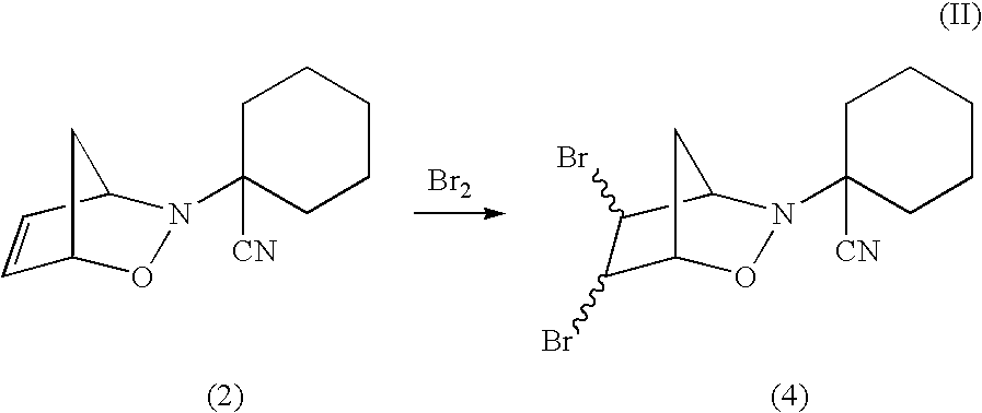
[0046]Formation of N-(1-Cyanocyclohexyl)bicyclo[2.2.1] 4,5-dibromo-3,6-dihydro-1,2-oxazine 4 and activation thereof with iodide to release neutral nitric oxide.
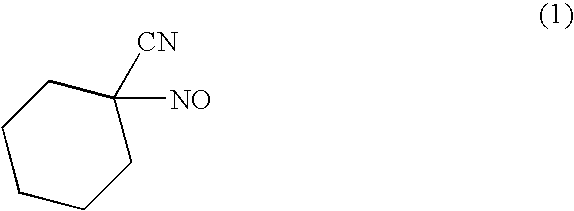
[0047]α-Cyano-C-nitroso compounds were synthesized from the corresponding ketone according to literature methods (Rehse, K.; Herpel, M. Pharm. Med. Chem. 1998, 331, 104-110; Gowenlock, B. G.; Pfab, J.; Kresze, G. Leibigs Ann. Chem. 1975, 1903-1913; Gregor, V. Coll. Czech. Chem. Comm. 1958, 23, 1782; DiStillo, A., Medana, C.; Ferrarotti, B.; Gasco, L; Ghigo, D.; Bosia, A.; Martorana, P. A.; Gasco, A. Pharm. Res. 2000, 41, 469-474).
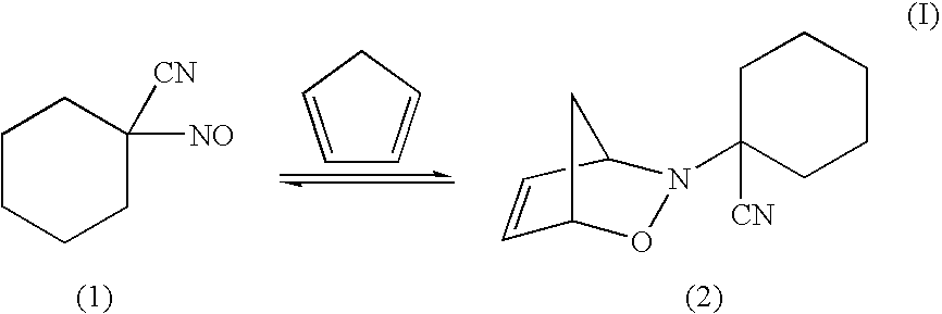
[0048]Diel's Alder adduct 2 was formed from 1 as follows:
[0049]Treatment of 1 with excess cyclopentadiene in benzene at 25° C. resulted in loss of the characteristic blue color of the C-nitroso species. At 0° C., a white solid, presumed to be 2, precipitated from solution. On warming, the solid turned blue, suggesting retro Diels Alder reaction and re-generation of 1. To confirm the identity of 2, hy...
working example ii
Forming Compounds (5) and (6)
[0058]
[0059]N-(1-Cyanocyclohexyl) bicyclo [2.2.1] 4,{tilde over (5)}-thiirane-3,6-dihydro-1,2-oxazine (5): A solution of 3 (80 mg, 0.43 mmol) in DCM under ice was treated with diethoxyoxophosphoranesulfenyl chloride (0.1 mL). Work up of the reaction mixture after 4 h, and flash chromatography affords the corresponding thiirane, as a mixture of diasteromers.
[0060]N-(1-Cyanocyclohexyl) bicyclo [2.2.1] 4-thio-5-hydroxy-3,6-dihydro-1,2-oxazine (6): A solution of N-(1-Cyanocyclohexyl) bicycle [2.2.1] 4,5-thiirane-3,6-dihydro-1,2-oxazine was treated with methanesulfenyl bromide to produce the 5-bromo derivative as the methyl disulfide. Treatment of the 5-bromo derivative with sodium acetate produces the corresponding acetate which, after reductive cleavage of the acetate and reduction of the disulfide with sodium borohydride provides the required 4-thio-5-hydroxy dihydrooxazine as a mixture of stereoisomers.
working example iii
Treatment of Patient with Chronic Hypertension with 4
[0061]A 60 year old male being treated with sodium iodide for hyperthyroidism has chronic hypertension (BP of 165 / 90). The patient is given 4 intravenously to maintain a blood concentration of 10 nanomolar. Blood pressure reduces to 140 / 85.
PUM
| Property | Measurement | Unit |
|---|---|---|
| homolytic bond energy | aaaaa | aaaaa |
| molecular weight | aaaaa | aaaaa |
| pKa | aaaaa | aaaaa |
Abstract
Description
Claims
Application Information