Modular percutaneous valve structure and delivery method

Inactive Publication Date: 2010-07-22
VALVE MEDICAL
View PDF69 Cites 177 Cited by
  • Summary
  • Abstract
  • Description
  • Claims
  • Application Information

AI Technical Summary

Benefits of technology

[0016]Device modules may also be fixed in place by friction or other positive location forces such as magnetic forces, interference fit or tight fit. Pull wires or push-rods may be used to position the valve sections relative to one another during assembly of the valve sections to form the valve assembly, and may also be used to assist in positioning the valve module (e.g., the valve assembly) within the support structure when combining the device modules to form the assembled valve device. Pull wires may also serve to tether device modules during delivery, so that the modules may be delivered and deployed in tandem.
[0017]Also provided is a system for valve delivery that permits valve function to be maintained while the modular valve device is assembled and placed at the site of implantation, and a method of maintaining valve function while assembling and implanting a percutaneous modular valve device with precision, by providing a temporary valve. In one embodiment, the temporary valve may be part of the delivery system (e.g., attached to the delivery device) and may be removed when the delivery system is extracted from the vessel. In another embodiment, the temporary valve may be mounted on the support structure of the permanent valve device, and implantation of the valve module of the permanent valve (e.g., leaflets substructure, valve assembly or individual valve sections) may crush or flatten the temporary valve leaflets. The method

Problems solved by technology

A malfunctioning valve fails to maintain the bodily fluid flow in a single direction with minimal pressure loss.
However, current artificial percutaneous prosthetic valves have the disadvantage of being extremely bulky, even when compressed for delivery.
The problem with this bulkiness is that it requires the delivery catheter to have a rather large diameter.
Large catheters generally are not suitable for percutaneous procedures and require cut-down procedures and a surgeon and/or sophisticated and difficult puncture-closure techniques.
The bulkiness and large diameter of current valve devices and delivery systems combined with the anatomy through which the devices must be delivered also can make delivery into the lumen problematic from the point of view of success rate, accuracy of deployment, and risk of complications.
Specifically, delivery complications may arise due to the shape of the lumen, for example, the significant natural curve of the aortic arch and/or a tortuous iliac/femoral artery through which the cat

Method used


Image

  • Modular percutaneous valve structure and delivery method
  • Modular percutaneous valve structure and delivery method
  • Modular percutaneous valve structure and delivery method

Examples


Embodiment Construction

[0036]The present invention provides implantable modular percutaneous prosthetic valve devices, systems and methods for percutaneously delivering and deploying implantable percutaneous modular heart valve devices and other implantable percutaneous modular valve devices in body lumens. The invention provides a modular prosthetic valve system that allows a prosthetic valve device to be delivered safely into a lumen without the need for invasive surgery.

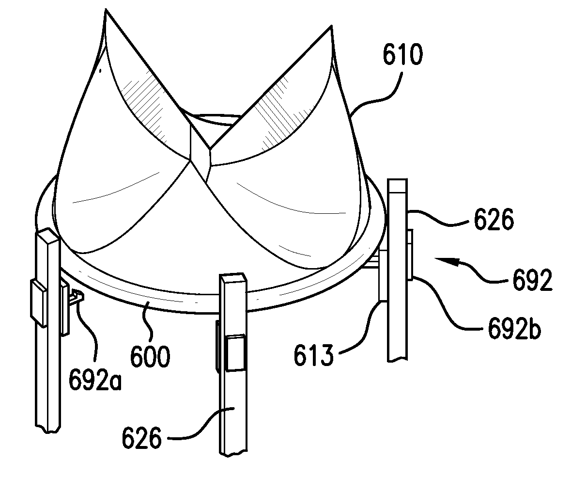
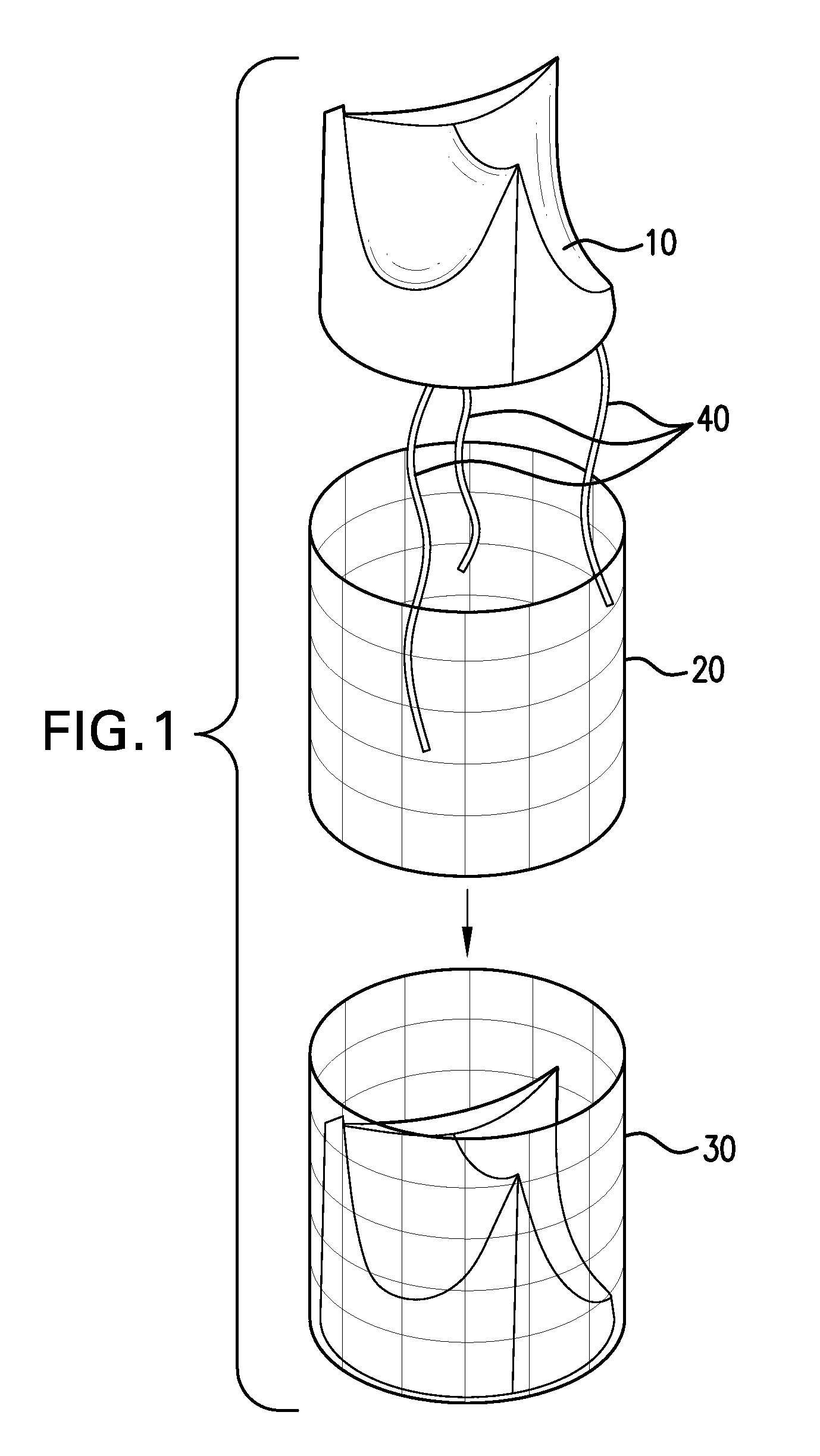
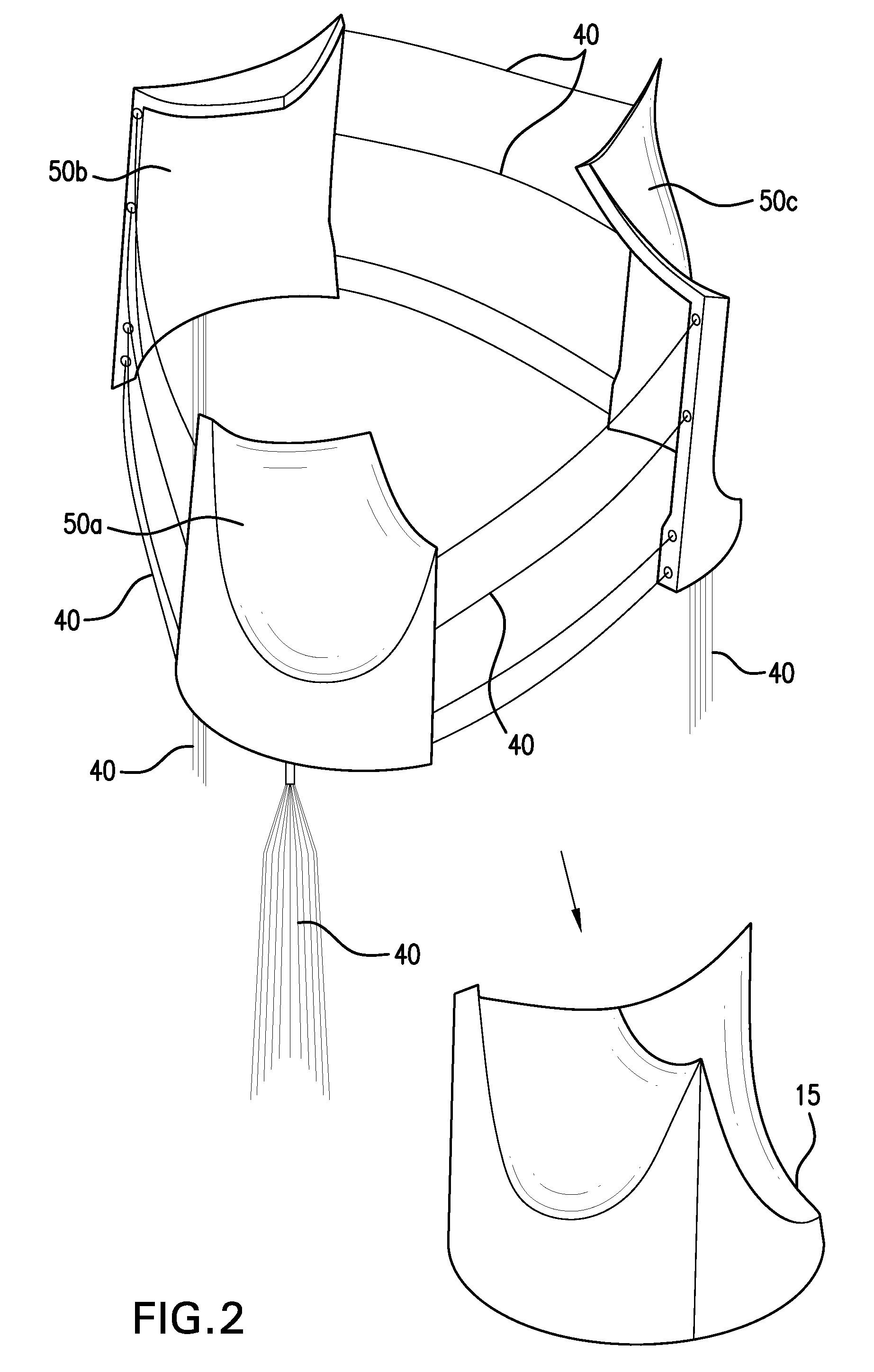
[0037]The artificial valve device of the invention comprises a plurality of device modules for delivery and assembly in vivo. The device modules may be delivered to a desired location in the body, for example near the site of valve implantation, at the site of valve implantation, or at a location some distance from the site of implantation, where they may be assembled to form the assembled valve device. From a functional perspective, the plurality of device modules may include a support structure and a valve module. The support structur...


PUM

PropertyMeasurementUnit
Diameteraaaaaaaaaa
Flexibilityaaaaaaaaaa

Abstract

A modular prosthetic valve device for implantation in a patient is disclosed. The valve device is designed as two or more modules to be delivered unassembled and combined into an assembled valve device in the body—e.g., in the body at or near the site where implantation occurs. The two or more modules may be a support structure and a valve assembly. The valve assembly may be formed from two or more valve sections. Because the valve device of the invention is deliverable as modules, it may have a smaller delivery diameter than pre-assembled percutaneous valves and permits use of a delivery device of reduced diameter. Delivering the valve device as modules increases the flexibility of the valve device during delivery, compared to percutaneous valve devices in the art. The invention further provides a system for and method of delivering such a modular valve device and assembling it in vivo. The modules of the valve device may be connected by pull wires for delivery sequentially to or near the implantation site in the body lumen, and then assembled by remote manipulation using the pull wires. The system may further include a temporary valve that may be deployed to maintain valvular function while the device modules are assembled. The temporary valve may be attached to the delivery device and deployed either before or after the support structure is expanded, or the temporary valve may be attached to the support structure and deployed when the support structure is expanded. Various locking mechanisms are provided for attaching the device modules together.

Description

[0001]This application claims benefit of priority of U.S. Provisional Application Ser. No. 61 / 144,007, filed Jan. 12, 2009.FIELD OF INVENTION[0002]The present invention relates to prosthetic valve devices for implantation in the body and methods of deployment thereof. In particular, the invention relates to a multi-component, or modular, percutaneous prosthetic valve device—a prosthetic valve capable of being delivered in parts and assembled in the body, and therefore capable of having a smaller delivery diameter than fully assembled percutaneous valve devices. The invention also relates to a system comprising such a modular valve device and a delivery device having a reduced diameter compared to a delivery device for a fully assembled percutaneous valve device, and a method of delivering and deploying such a modular valve device using the reduced diameter delivery device system. The invention further relates to a method of assembling a modular valve device including locking the dev...

Claims


Application Information

Patent Timeline
IPC IPC(8): A61F2/24B23P11/00
CPCA61F2/2409A61F2/2412A61F2/2418A61F2/2439A61F2250/0008A61F2250/006A61F2230/0091Y10T29/49826A61F2220/0033A61F2250/0004A61F2/00A61F2/24A61F2/2427
Inventor RICHTER, YORAMRICHTER, JACOB
Owner VALVE MEDICAL
Why Eureka
Try Eureka