
Carbide cutting tool and method of making such a tool

a cutting tool and carbide technology, applied in the field of cutting tools, can solve the problems of increasing the downtime of production tools, affecting the quality of sintering monobloc tools, etc., and achieves the effects of improving the working life, simple and economical, and less expensiv

Active Publication Date: 2010-07-29
PRECICARB SA
View PDF29 Cites 12 Cited by
  • Summary
  • Abstract
  • Description
  • Claims
  • Application Information

AI Technical Summary

Benefits of technology

[0014]In particular, the invention aims to provide a cutting tool for a granulator whose working life is significantly increased.
[0015]The invention also aims to provide a cutting tool which is less expensive than the tools of the state of the art in terms of manufacture and repair.
[0016]A further aim of the invention is to provide a simple and economical method of making and grinding the cutting tool according to the invention.MAIN CHARACTERISTIC FEATURES OF THE INVENTION
[0019]As an advantage, the mechanical fixing of the blades to the spindle is achieved by screwing, tightening, brazing, shrinking, crimping or sticking.
[0031]As an advantage, the spindle has movable locking parts in the form of rods of the same length as the blades, which can be set axially along the latter and which form slots when they are in position, said locking parts comprising spaces for inserting screws for fixing to the spindle.

Problems solved by technology

In the case of the above mentioned granulators used in production, it is necessary to replace the worn monobloc cutting tools up to several times a day, which increases the downtimes of the production tool and puts a strain on productivity (up to several hours of downtime a day).
The use of carbide, especially in the form of monobloc tools, allows the working life of the cutting tool to be increased by 5 to 10 times. However, monobloc tools produced by sintering are expensive and the deterioration of a single blade entails the replacement of the whole tool.
The positioning and fixing of the individual blades on said body are extremely delicate operations given the tolerance to be observed for the final grinding, all the more so for helical blades.

Method used


Image

  • Carbide cutting tool and method of making such a tool
  • Carbide cutting tool and method of making such a tool
  • Carbide cutting tool and method of making such a tool

Examples


Embodiment Construction

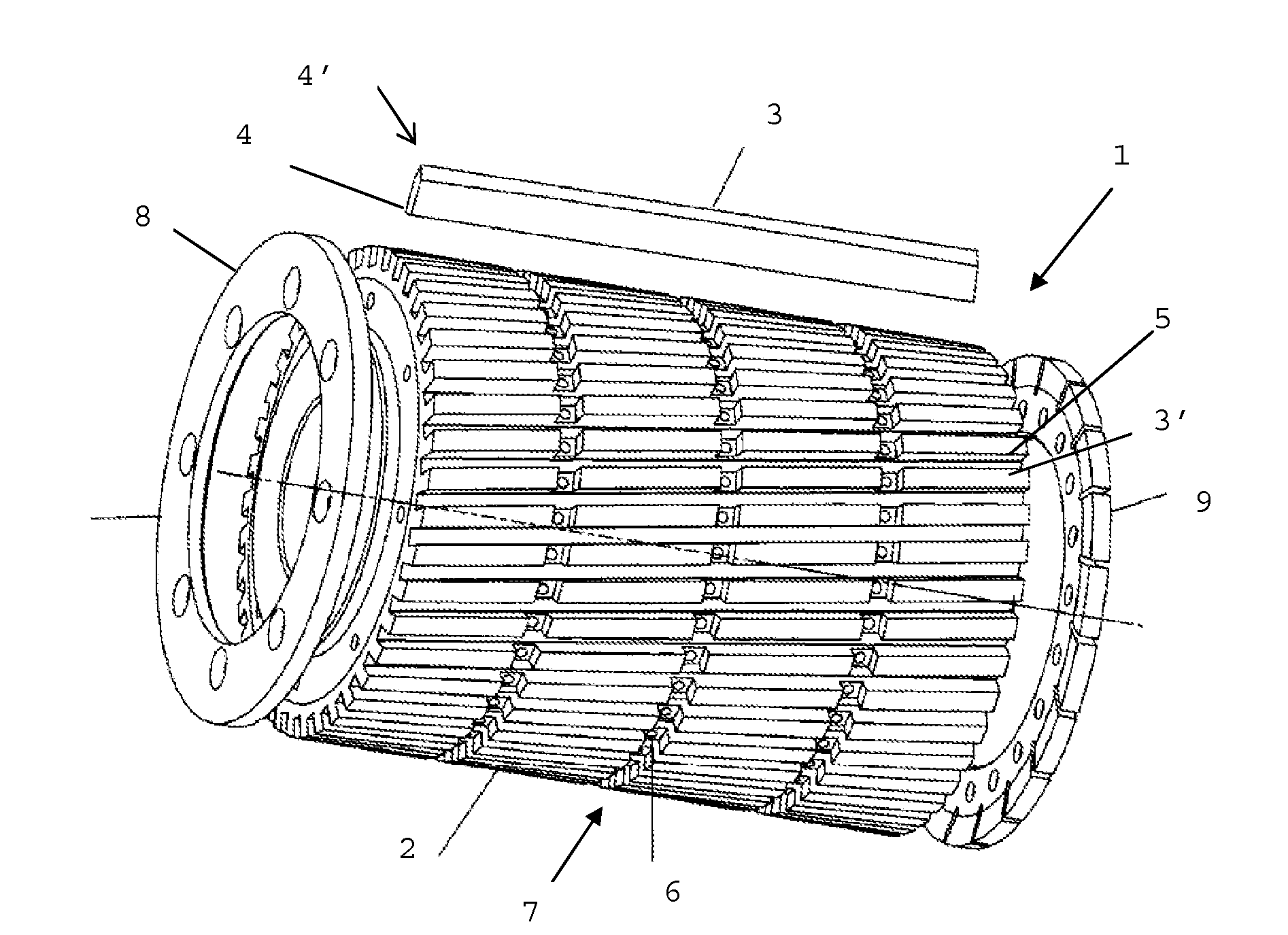
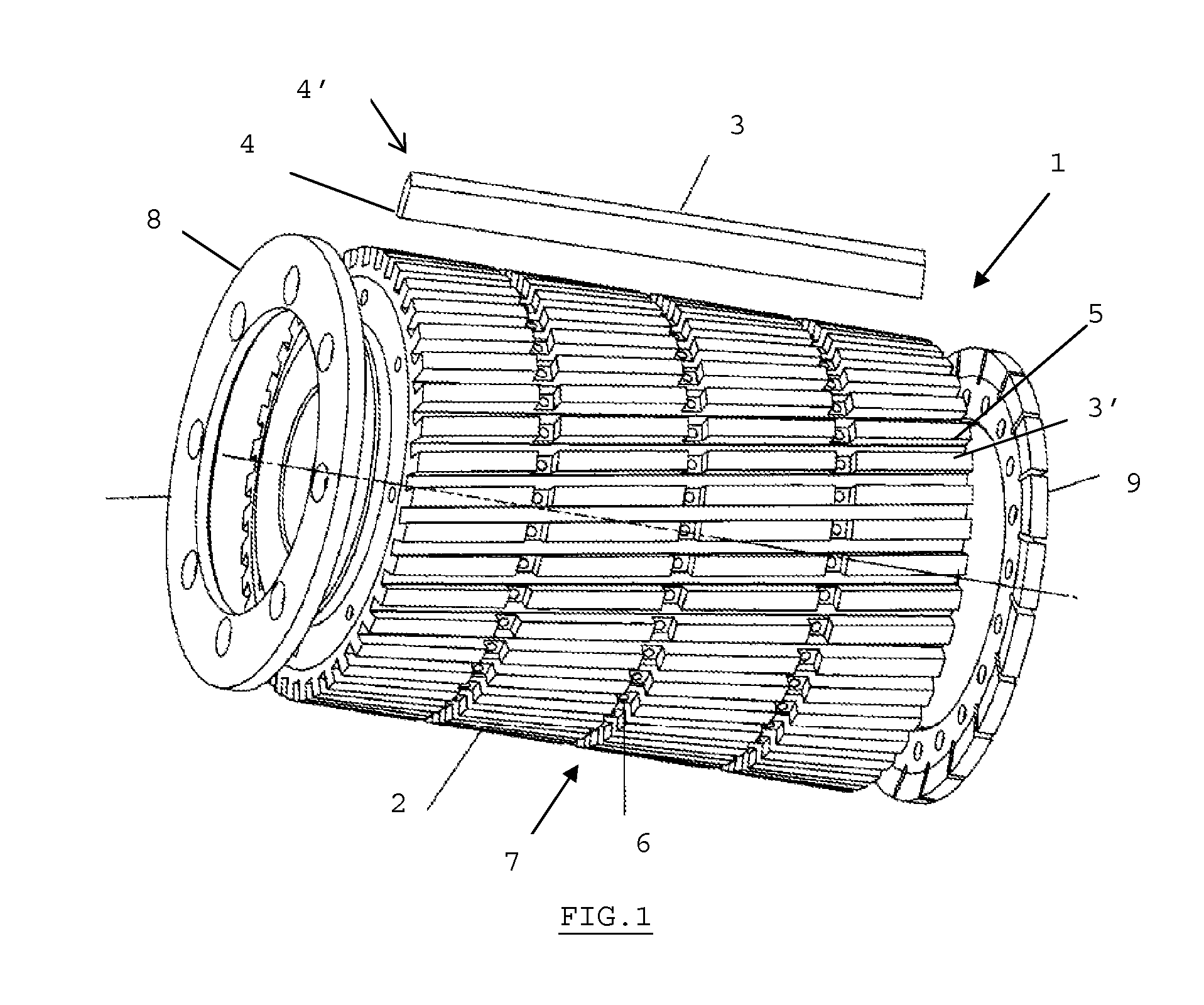
[0043]As shown in FIG. 1, the cutting tool 1 according to a first preferred embodiment of the invention comprises a cylindrical spindle 2 supporting blades, made for example of ordinary steel or stainless steel. The blades 3, on the other hand, are made of a material with great resistance to wear such as, for example, tungsten carbide (WC), ceramics, high-speed steel etc., possibly coated with titanium nitride (TiN), titanium carbonitride (TiCN), titanium aluminium nitride (TiAlN), chromium nitride (CrN) etc.

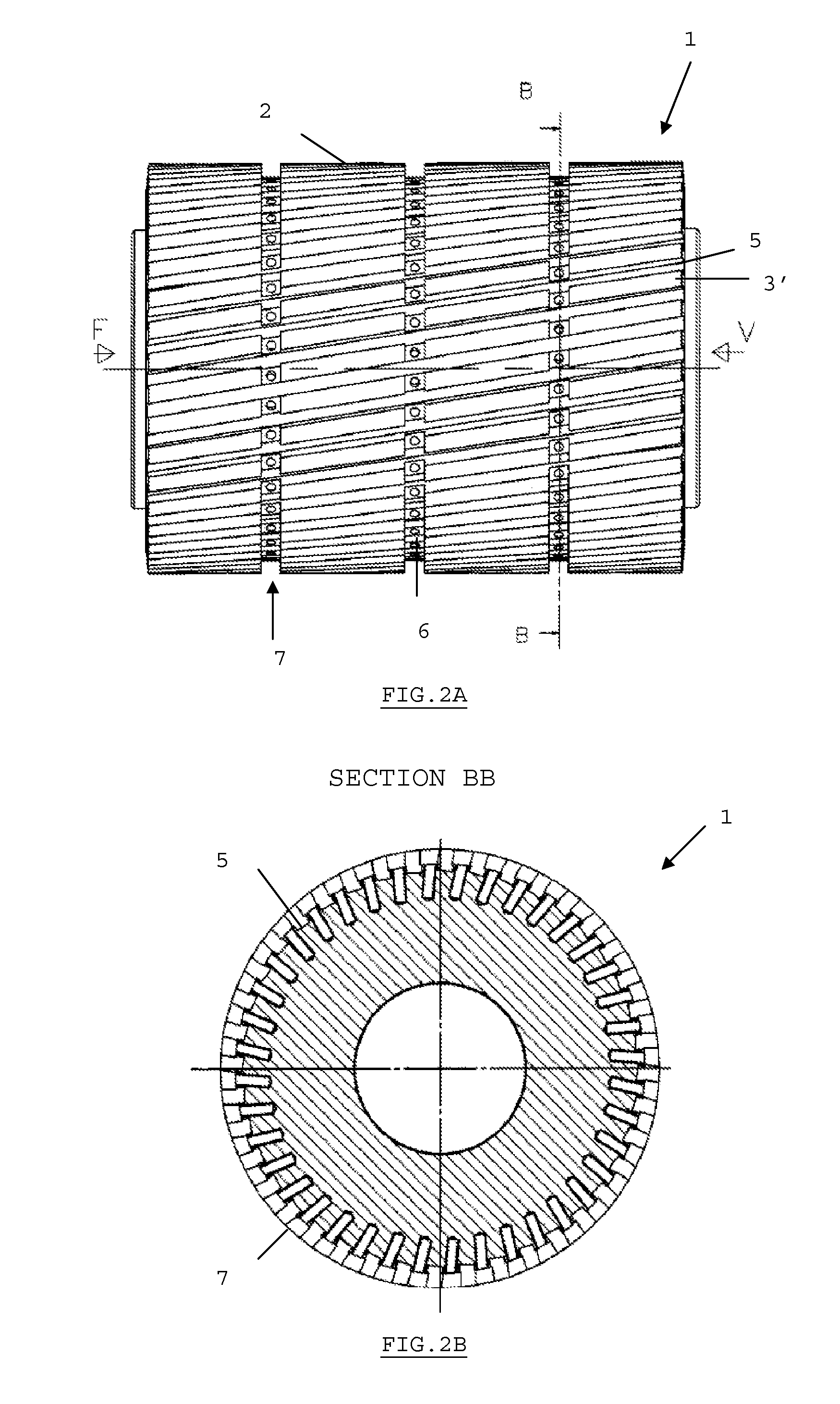
[0044]The rough blades or blade blanks (not shown) are essentially in the form of rectangular parallelipeds or bars with rectilinear bases that are roughly ground and fixed on the side surface of the cylindrical spindle 2 in slots 5 by mechanical means, for example by locking by means of cone-headed screws 6. The blades 3 are orientated parallel to each other at an angle of about 10 degrees relative to the axis of the cylinder 2. This angle will allow the grinding blades with a ...


PUM

PropertyMeasurementUnit
Angleaaaaaaaaaa
Angleaaaaaaaaaa
Angleaaaaaaaaaa

Abstract

The present invention concerns a rotary cutting tool (1) with a cylindrical supporting spindle (2) and several individual blades (3) with essentially radial cutting edges, helically ground and set at regular intervals on the outer surface of the spindle, each blade (3) having a rectilinear base (4) which inserts into a slot (5) of the same shape as said base, each individual blade (3) being mechanically fixed to the spindle (2), characterized in that it also comprises two covers (8, 9) fixed to the respective bases (8′, 9′) of the spindle (2) so as to reinforce the fixing of the blades (3).

Description

SUBJECT OF THE INVENTION[0001]The present invention concerns a cutting tool with knives or blades with increased resistance to wear, in particular for cutting any synthetic or mineral material in a thread (plastic, glass fibre etc.), coated or not, into granules before using it as a raw material.[0002]The invention concerns a rotary cutting tool with several individual cutting edges set at regular intervals or not around an axis.[0003]The invention also concerns a method of making such a tool.STATE OF THE ART AND SETTING OF THE PROBLEM[0004]In the manufacture or recycling of plastic materials, for example, granulators are known that comprise an extruder or a spool that work according to a “mincing” principle. In the case of the extruder, the plastic material is heated and the molten mass is pushed through a disc with holes.[0005]The emerging threads are then cut into granules by rotary blades. The cutting edges of these blades are generally helical for a better distribution of the l...

Claims


Application Information

Patent Timeline
IPC IPC(8): B23C5/04B23C5/22B23P15/34
CPCB02C18/186B23C5/04B23C5/22B23C2224/24Y10T407/27B23C2224/36B23C2226/18Y10T407/1934Y10T407/1942B23C2224/32B26D1/36B23D25/12
Inventor KERF, GERARD
Owner PRECICARB SA
Learn More