
Methods for the formation of disulphide bonds

a disulphide and bonding technology, applied in the field of disulphide bonding methods, can solve the problems of loss of most interesting binders which bind with high affinity to the target, none of the studies above describe, etc., and achieve the effects of increasing the reactivity of said cysteine residues, increasing functional display rate, and increasing display ra

Active Publication Date: 2010-07-29
MORFOZIS AG
View PDF30 Cites 0 Cited by
  • Summary
  • Abstract
  • Description
  • Claims
  • Application Information

AI Technical Summary

Benefits of technology

[0014]Thus, the present invention provides an improved method for the formation of a disulphide bond between a first cysteine residue comprised in a first (poly)peptide / protein and a second cysteine residue comprised in a second (poly)peptide / protein, preferably a different (poly)peptide / protein. Said improvement shall preferably lead to a higher reactivity of said cysteine residues, thereby conferring an increased display rate, in particular a, increased functional display rate.
[0016]In particular embodiments, the present invention provides an improved system for the display of (poly)peptides / proteins on the surface of bacteriophage particles without the need to use fusion proteins with phage coat proteins. The higher reactivity of said cysteine residues thereby leads to a higher display rate, in particular a higher functional display rate.
[0019]In certain embodiments the present invention provides a method to display a second (poly)peptide / protein on the surface of a bacteriophage particle comprising: causing or allowing the attachment of said (poly)peptide / protein after expression to a member of the protein coat, wherein said attachment is caused by the formation of a disulphide bond between a first cysteine residue comprised in said member of the protein coat and a second cysteine residue comprised in said (poly)peptide / protein, wherein said (poly)peptide / protein or said member of the protein coat comprises an amino acid with a pI greater than 8 which positively affects the reactivity of said first or said second cysteine residue.

Problems solved by technology

However, the most interesting binders which bind with high affinity to the target might be lost by that approach.
However, none of the studies above describe a system in which an intermolecular disulphide bond is formed between a first (poly)peptide / protein and a second, different, (poly)peptide / protein.
In particular, in none of these studies is such a disulphide bond formed in the periplasmatic space of a host cell.

Method used


Image

  • Methods for the formation of disulphide bonds
  • Methods for the formation of disulphide bonds
  • Methods for the formation of disulphide bonds

Examples


example 1

Construction of Novel Vectors

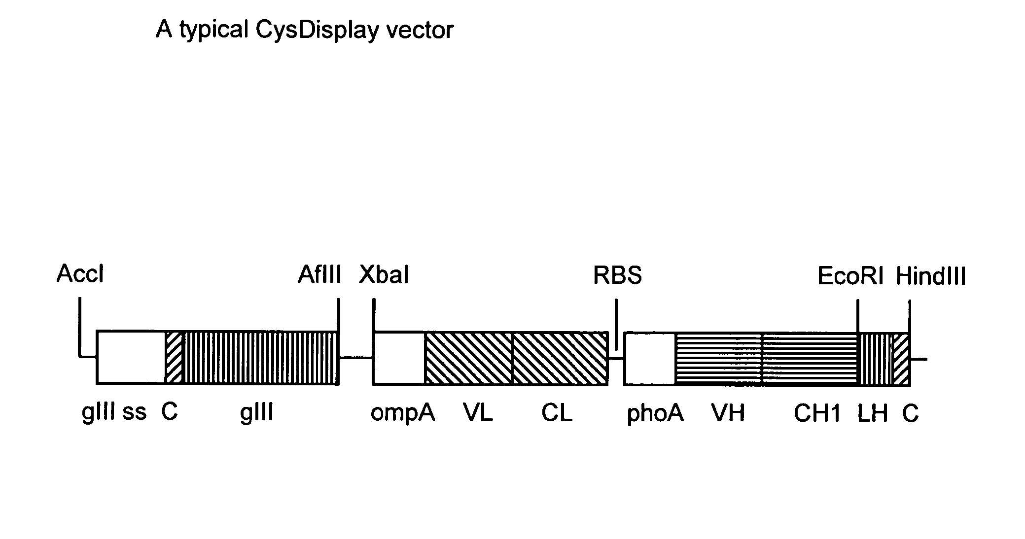
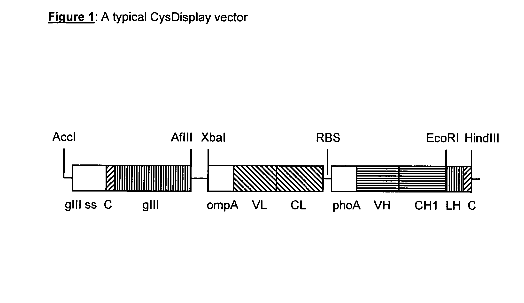
[0166]Vectors are based on known expression vectors described in WO 01 / 05909. Heavy and light chains of Fab fragments are expressed from a dicistronic phagemid under the control of the lac promotor / operator region. The first expression cassette comprises the signal sequence ompA and the variable and constant domain of the light chain. The second expression cassette comprises the signal sequence phoA and the variable and constant domain of the heavy chain. Heavy and light chain are not linked via a disulfide bond. Gene III is also encoded on the same vector. The cysteine residues forming the disulphide bond are located at the N-terminus of pIII and at the C-terminus of the heavy chain Fd-fragment. The main features of a typical CysDisplay vector are shown in FIG. 1.

[0167]New display vector variants (pMORPH25 versions A, B, C and E) have been constructed based on the pMORPH25 vector, which is a derivative of pMORPH23 (described in WO 04 / 013276). The sequen...

example 2

Phage Binding to Ni-NTA Plates

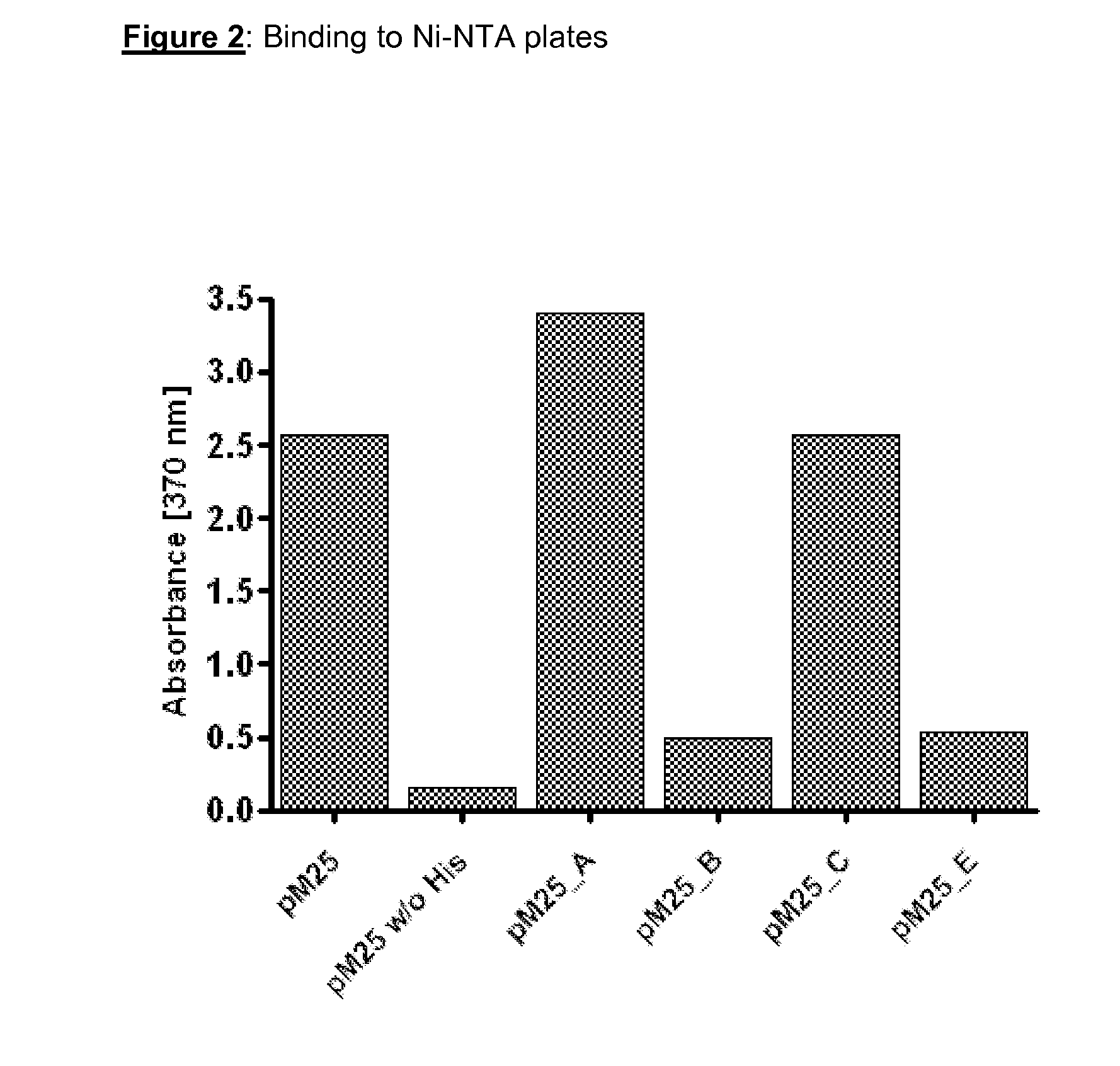
[0171]The six histidine residues directly N-terminal to the reactive cysteine residue in pMORPH25 confer the bacteriophage particles with the capability to bind to Ni-NTA plates. In version A a lysine residue was introduced C-terminal to the reactive cysteine residue. In versions B, C and E of pMORPH25 this stretch of six histidine residues was destroyed by way of introduction of at least one lysine residue into each of said hexa-histidine stretches. Presumably, this should lead to a loss of the capability of the bacteriophage particles displaying the Fab fragments to bind to Ni-NTA plates.

[0172]Bacteriophage particles displaying Fab fragments were produced via standard techniques (see e.g. Kay et al, 1996 and Example 2.2 of WO 01 / 05909). Binding of bacteriophage particles to Ni-NTA plates was determined as briefly outlined. Phage particle (8×10⁸ / well), which were pre-incubated for 2 hours with blocking solution (Chemiblock diluted with TBS, 0.1% Tween2...

example 3

Relative Display Rate

[0174]The relative display rate of phage particles of the various vector constructs (version A-version E, as outlined in Example 1) were determined as described below.

[0175]Phage particles were produced by standard procedure (see e.g. Kay et al, 1996 and Example 2.2 of WO 01 / 05909). The phage particle number and the antibody display rate of an unknown phage particle solution was determined in two independent ELISA experiments.

[0176]The Phage particle titer of a phage preparation is determined via an anti-pIII capture ELISA, and the antibody display rate of a phage preparation was determined via an anti-Fd capture ELISA. The relative display rate is defined as the anti-Fd signal divided by the anti-pIII capture ELISA signal.

[0177]Maxisorp Nunc-Immuno microtiter plates were coated with 100 μl of a 2.5 μg / ml anti-pIII capture antibody solution (MoBiTech, Göttingen, Germany) and a second plate with 100 μl of 0.5 μg / ml anti-Fd capture antibody solution for 12 hours a...


PUM

PropertyMeasurementUnit
temperatureaaaaaaaaaa
nucleic acidaaaaaaaaaa

Abstract

The present invention relates to methods for the formation of inter-molecular disulphide bonds, including (poly)peptides / proteins, nucleic acids, vectors, host cells and bacteriophages used in these methods. Furthermore the invention relates to the use of this method for the improved display of (poly)peptides / proteins on the surface of bacteriophage particles.

Description

[0001]A number of documents are cited throughout this specification. The disclosure content of these documents is herewith incorporated by reference in their entirety.BACKGROUND OF THE INVENTION[0002]In 1985, Smith first demonstrated that filamentous phages tolerate foreign protein fragments inserted in their gene III protein (pIII), and could show that the protein fragments are presented on the phage surface (Smith, 1985). Ladner extended this concept to the screening of repertoires of (poly)peptides and / or proteins displayed on the surface of phage particles (WO 88 / 06630; WO 90 / 02809). Since then, phage display has experienced a dramatic progress and resulted in substantial achievements.[0003]Various formats have been developed to construct and screen (poly)peptide / protein phage-display libraries, and a large number of review articles and monographs cover and summarise these developments (e.g., Kay et al., 1996; Dunn, 1996; McGregor, 1996). Most often, filamentous phage-based syst...

Claims


Application Information

Patent Timeline
Patent Type & Authority Applications(United States)
IPC IPC(8): C12N7/00C07K1/00C07K16/00C07H21/00
CPCC07K16/005C07K19/00C40B50/06C12N15/1037C07K2317/55
Inventor PRASSLER, JOSEFSTARK, YVONNE
Owner MORFOZIS AG
Learn More