
Fuel cell, fuel cell metal separator, and fuel cell manufacturing method

a metal separator and fuel cell technology, applied in the direction of sustainable manufacturing/processing, paper/cardboard containers, final product manufacturing, etc., can solve the problems of weak adhesive strength, increased detachment risk, and problems that have been subjected to surface treatment coating across the entire separator surface, and achieve excellent sealing properties and corrosion resistance.

Inactive Publication Date: 2010-08-05
TOYOTA JIDOSHA KK
View PDF8 Cites 18 Cited by
  • Summary
  • Abstract
  • Description
  • Claims
  • Application Information

AI Technical Summary

Benefits of technology

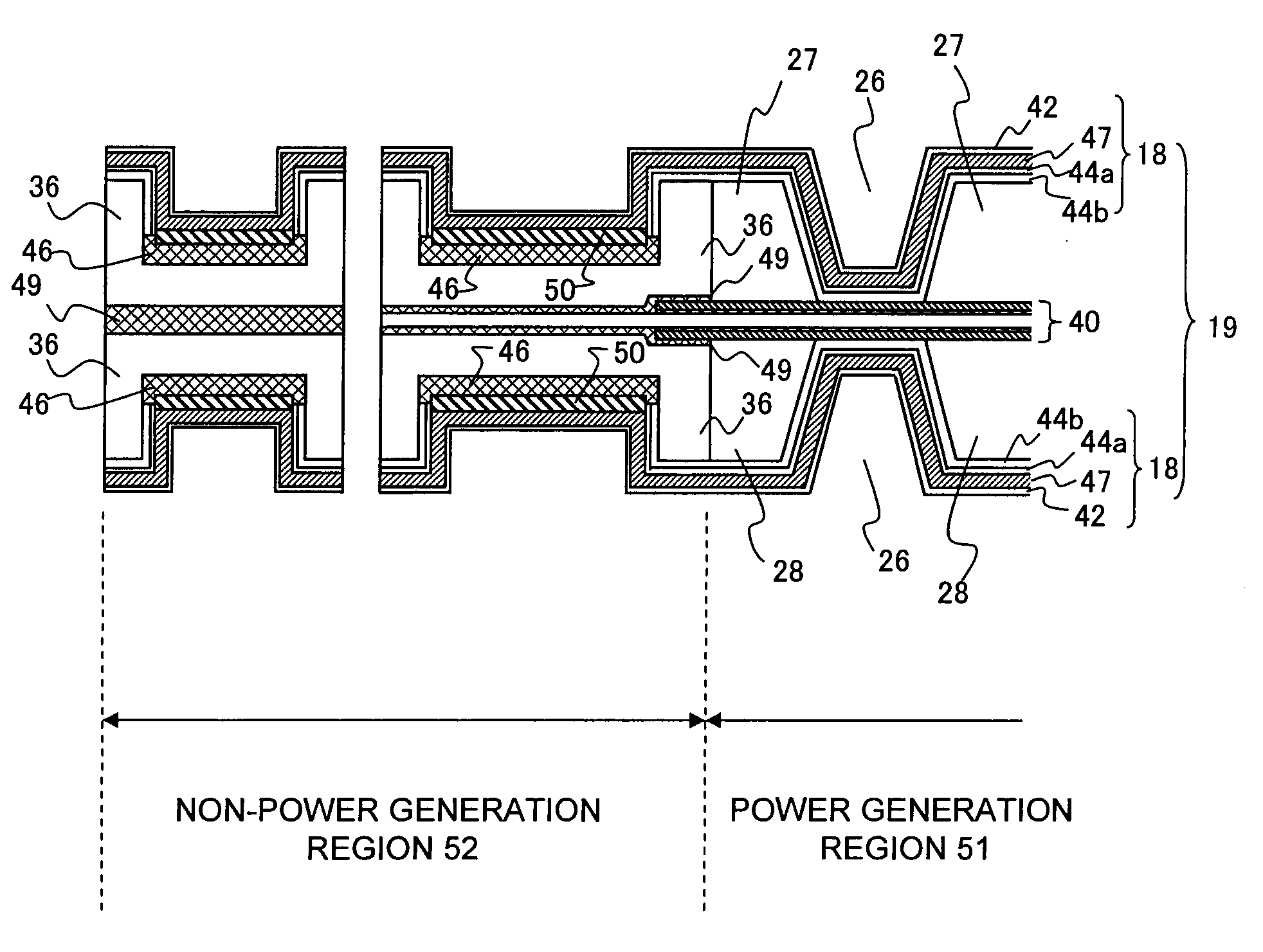
[0034]The present invention, by providing a resin layer on at least a portion of an adhesion region where a metal separator contacts an adhesive layer, is able to provide a fuel cell and a fuel cell separator having seal structures that exhibit excellent sealing properties and corrosion resistance. Furthermore, the present invention is also able to provide a method of manufacturing such a fuel cell.

Problems solved by technology

However, metal separators that that have been subjected to surface-treatment coating across the entire separator surface suffer from the problems outlined below.
Generally, a noble metal coating is chemically inert with respect to adhesives, corrosion-resistant coatings and metal separator substrates, and because the coating relies mainly on close physical adhesion, it tends to suffer from weak adhesive strength, and is more likely to undergo detachment than the adhesion achieved between adhesives and metal separator substrates.
(1) detachment of the adhesive from the noble metal coating,
(2) detachment of the noble metal coating from the separator substrate, and
(3) detachment of the corrosion-resistant coating from either the noble metal coating or the separator substrate.
Even if the initial sealing properties are satisfactory, if detachment occurs, then the sealing properties at the sealed portions can no longer be ensured, making it difficult to achieve sustained sealing properties.
Further, if the corrosion-resistant coating inhibits curing of the adhesive, then achieving satisfactory initial sealing properties may also be problematic.
In a structure such as that disclosed in Patent Document 1, where an adhesive makes direct contact with the metal separator substrate at an uncoated portion on the metal separator, because no surface-treatment coating exists at the joint region, there is a possibility that corrosion may start at that joint region while it is still exposed.
Further, in a structure such as that disclosed in Patent Document 2, where a metal separator substrate and a resin frame are bonded together directly without any adhesive layer provided therebetween, the lack of an adhesive layer at the joint region increases the likelihood of detachment, meaning corrosion may start at that joint region when it is exposed.
Furthermore, even if an adhesive layer formed using the type of electrodeposition described in Patent Document 3 is used for bonding a metal separator having a noble metal coating to a resin frame, the types of detachment problems described above can still not be entirely resolved.

Method used


Image

  • Fuel cell, fuel cell metal separator, and fuel cell manufacturing method
  • Fuel cell, fuel cell metal separator, and fuel cell manufacturing method
  • Fuel cell, fuel cell metal separator, and fuel cell manufacturing method

Examples


example 1

[0106]An SUS metal separator substrate (450 mm×200 mm×0.1 mm) is molded into a predetermined separator shape using a press method, the metal separator substrate is masked, and an electrodeposition method is used to form a polyamideimide film (film thickness: 20 μm) within an adhesion region. Subsequently, electroplating is used to form a gold plating (thickness: 0.1 μm) on the regions other than the adhesion region where the polyamideimide film had been formed. A carbon coating (thickness: 30 μm) is then formed on top of the gold coating on the same side of the substrate as the polyamideimide film, thus completing preparation of a surface-coated metal separator.


PUM

PropertyMeasurementUnit
thicknessaaaaaaaaaa
thicknessaaaaaaaaaa
thicknessaaaaaaaaaa

Abstract

A fuel cell having a seal structure that exhibits excellent sealing properties and corrosion resistance. By providing a resin layer on at least a portion of an adhesion region where a metal separator contacts an adhesive, a fuel cell having a seal structure that exhibits excellent sealing properties and corrosion resistance can be provided.

Description

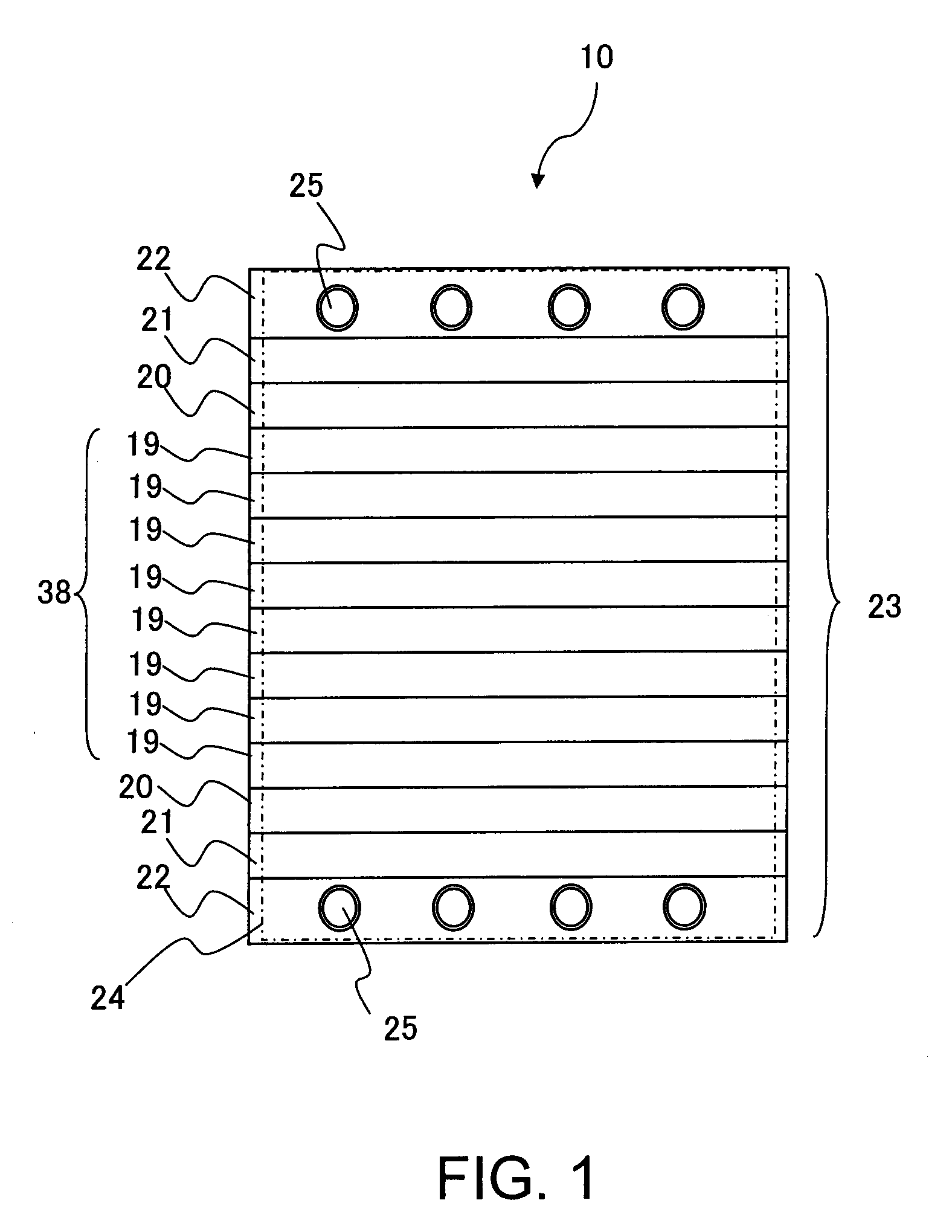
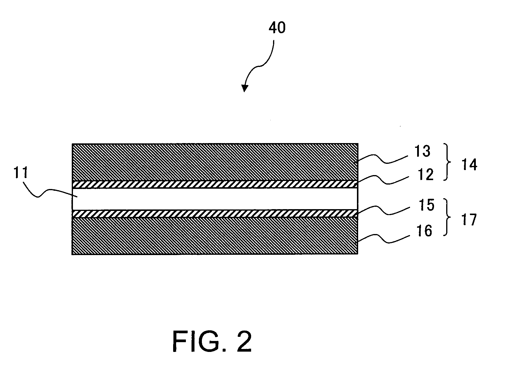
TECHNICAL FIELD[0001]The present invention relates to a fuel cell, a fuel cell metal separator, and a method of manufacturing a fuel cell.BACKGROUND ART[0002]Fuel cells, which generate electricity by converting chemical energy to electrical energy via an electrochemical reaction that uses, as raw materials, an oxidizing gas such as oxygen or air, and a reducing gas (a fuel gas) such as hydrogen or methane or a liquid fuel such as methanol are attracting considerable attention as one possible countermeasure to environmental problems and resource problems.[0003]A unit fuel cell (unit cell) is formed by sandwiching a membrane electrode assembly (MEA), in which a fuel electrode (an anode catalyst layer) provided on one surface of an electrolyte membrane and an air electrode (a cathode catalyst layer) provided on the other surface are disposed facing one another across the electrolyte membrane, between separators such as metal separators. A plurality of these unit cells are stacked toget...

Claims


Application Information

Patent Timeline
Patent Type & Authority Applications(United States)
IPC IPC(8): H01M8/10B32B37/02
CPCH01M8/0206H01M8/0228H01M8/0254Y10T156/10H01M8/0284H01M8/1004Y02E60/521H01M8/0273Y02P70/50Y02E60/50
Inventor KIMURA, KENJIKIM, JINHAKSHIRAHAMA, JUNICHIAONO, HARUYUKI
Owner TOYOTA JIDOSHA KK
Learn More