Multi mode radio frequency transceiver front end circuit

a transceiver and front end technology, applied in the field of single-band transmitreceiver front end integrated circuits, can solve the problems of reducing efficiency, reducing power, and difficult to achieve +20 dbm power levels at 1.8v,

Active Publication Date: 2010-08-19
SKYWORKS SOLUTIONS INC
View PDF32 Cites 185 Cited by
  • Summary
  • Abstract
  • Description
  • Claims
  • Application Information

AI Technical Summary

Benefits of technology

[0017]According to one embodiment of the present invention, a front end circuit for coupling an antenna to a first radio frequency (RF) transceiver and a second RF transceiver is contemplated. Each of the RF transceivers may have a respective one of a signal input, a signal output, a receive enable line and a transmit enable line. The front end circuit may include an antenna port connectable to the antenna. Additionally, the front end circuit may include a first power amplifier that is coupled to the signal output of the first RF transceiver. The first power amplifier may include a first transmit control circuit coupled to the transmit enable line of the first RF transceiver. The front end circuit may also include a first low noise amplifier that is coupled to the signal input of the first RF transceiver. The first low noise amplifier may include a first receive control circuit that is coupled to the receive enable line of the first RF transceiver. Furthermore, there may be a second power amplifier that is coupled to the signal output of the second RF transceiver. The second power amplifier may include a second transmit control circuit that is coupled to the transmit e...

Problems solved by technology

Although current draw is typically not an issue because of the existence of simple solutions involving multiple active devices connected in parallel, +20 dBm power levels at 1.8v have been difficult to achieve, particularly for signals having envelope variations, as is the case with OFDM, QPSK, QAM, and the like.
Increasing current draw introduces several new issues including decreased efficiency because of a greater proportion of power being lost as heat, and decreased battery life.
Considering that most RF circuits have a 50-Ohm impedance, the design of matching circuits for decreased impedance also becomes an issue, typically due to increased power losses.
Conventional WLAN transceivers typically do not generate sufficient power or have sufficient sensitivity necessary for reliable communications.
With regard to Bluetooth transceivers, however, 0 dBm output at the antenna may be sufficient for class-3 operation, while 4 dBm may be sufficient for class-2 operation, so additional amplification may not be required.
WLAN, Bluetooth, and ZigBee are understood to share the same operating frequency band, that is, ...

Method used


Image

  • Multi mode radio frequency transceiver front end circuit
  • Multi mode radio frequency transceiver front end circuit
  • Multi mode radio frequency transceiver front end circuit

Examples


first embodiment

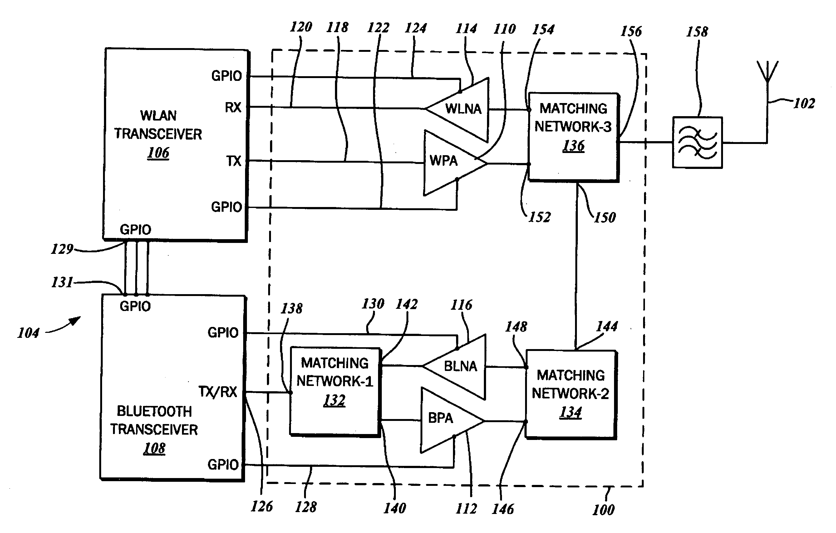
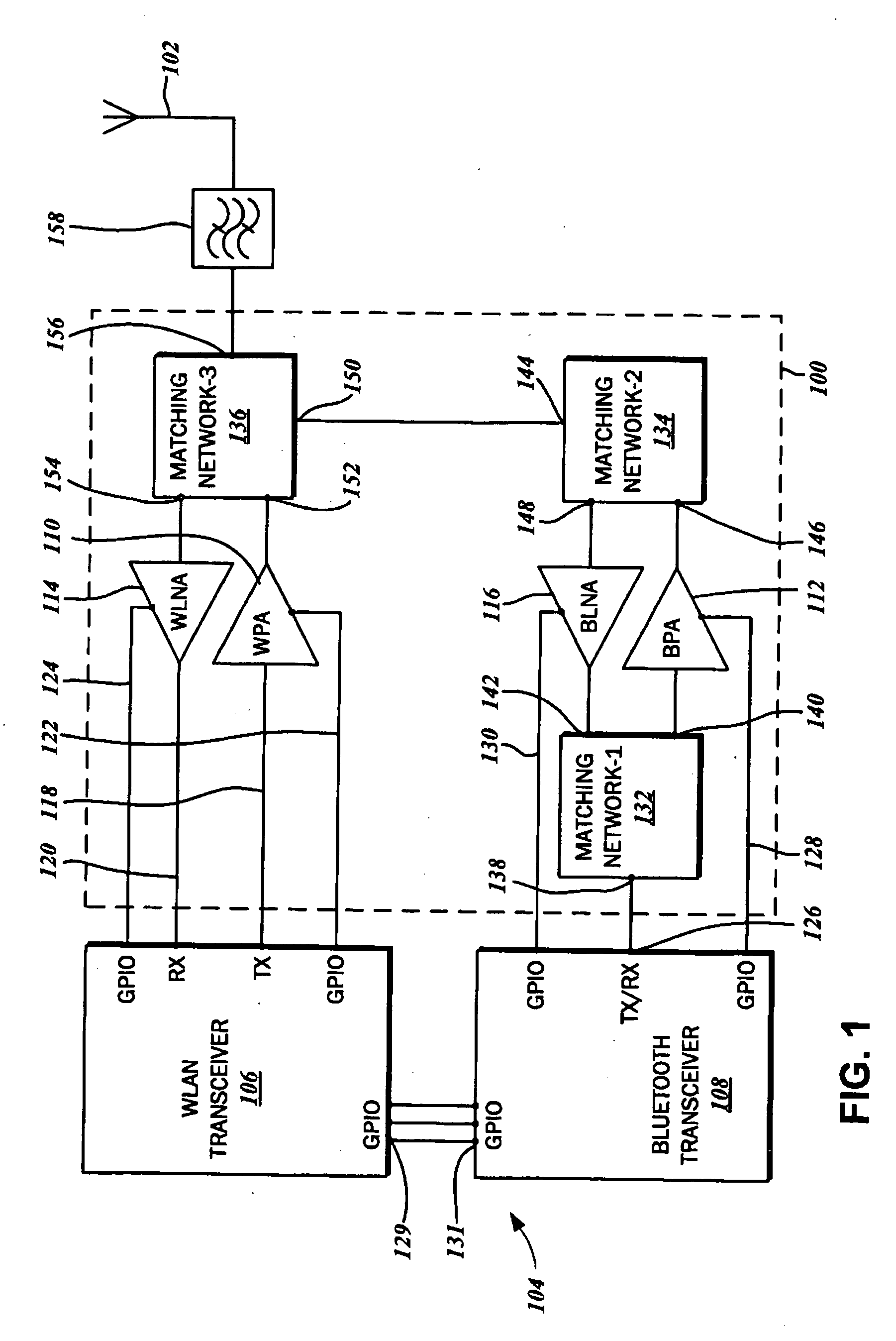
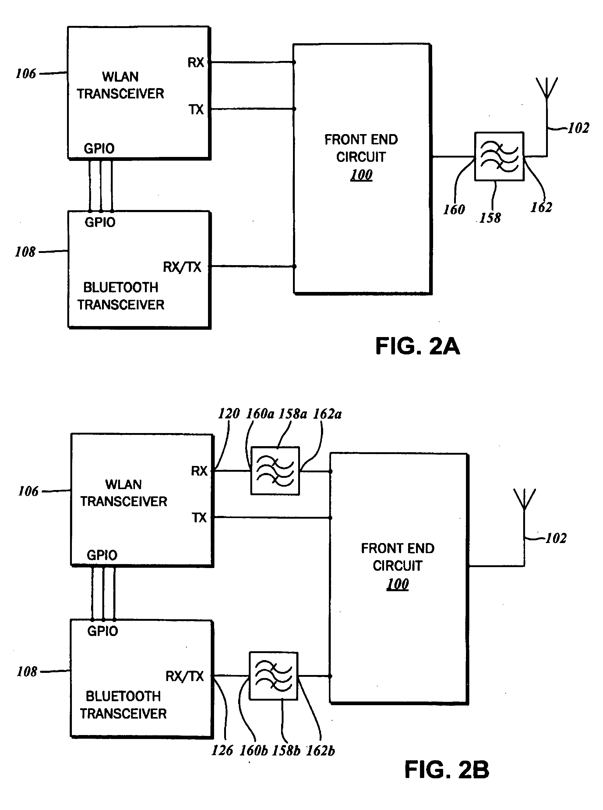
[0048]As best illustrated in FIG. 2A, a first embodiment contemplates the band pass filter 158 being disposed between the front end circuit 100 and the antenna 102. More particularly, the band pass filter 158 includes a first port 160 that is connected to the front end circuit, and a second port 162 that is coupled to the antenna 102. Referring back to the block diagram of FIG. 1, the first port 160 of the band pass filter may be coupled to a fourth port 156 of the third matching network 136. The band pass filter 158 is typically a low temperature co-fired ceramic (LTCC) or may be an integrated passive device (IPD / IPAD) that is fabricated on a GaAs substrate without an epitaxial layer, a sapphire substrate, or a glass substrate.

[0049]In a second embodiment shown in FIG. 2B, a first band pass filter 158a is disposed between the WLAN transceiver 106 and the front end circuit 100, and a second band pass filter 158b is disposed between the Bluetooth transceiver 108 and the front end cir...

second embodiment

[0078]With reference to the circuit diagram of FIG. 4, the front end circuit 100b is generally defined by a WLAN transmit block 300, a WLAN receive block 302, and a combined Bluetooth block 304. The various subparts thereof are understood to correspond to the aforementioned power amplifiers 110, 112, low noise amplifiers 114, 116, and the matching networks 132, 134, and 136, as will be detailed more fully below. The WLAN transmit block 300 includes the TX (transmit) port 170 that is connected to the WLAN transmit line 118, and the WLAN receive block 302 includes an RX (receive) port 172 that is connected to the WLAN receive line 120. Additionally, the Bluetooth block 304 includes the shared TX / RX port 174 that is connected to the common transmit and receive line 126 of the Bluetooth transceiver 108. The front end circuit 100b also includes an antenna port 175 associated with each of the WLAN transmit block 300, the WLAN receive block 302, and the combined Bluetooth block 304. The an...

third embodiment

[0091]Referring now to the schematic diagram of FIG. 5, the front end circuit 100c is defined by a WLAN transmit block 324, a WLAN receive block 326, and a combined Bluetooth block 328. The various subparts thereof are understood to correspond to the power amplifiers 110, 112, low noise amplifiers 114, 116, and the matching networks 132, 134, and 136, as will be detailed more fully below. The WLAN transmit block 324 includes the TX (transmit) port 170 that is connected to the WLAN transmit line 118, and the WLAN receive block 326 includes an RX (receive) port 172 that is connected to the WLAN receive line 120. Additionally, the Bluetooth block 328 includes the shared TX / RX port 174 that is connected to the common transmit and receive line 126 of the Bluetooth transceiver 108. The front end circuit 100c also includes an antenna port 175 associated with each of the WLAN transmit block 324, the WLAN receive block 326, and the combined Bluetooth block 328. The antenna matching block 169...


PUM


Abstract

A front end circuit for coupling an antenna to a first radio frequency (RF) transceiver and a second RF transceiver is contemplated. The RF transceivers have a signal input, a signal output, a receive enable line and a transmit enable line. In addition to an antenna port, the front end circuit has a first power amplifier and a first low noise amplifier both coupled to first RF transceiver, and a second power amplifier and a second low noise amplifier both coupled to the second RF transceiver. The front end circuit includes a matching network that couples the power amplifiers and the low noise amplifiers, the various outputs and inputs thereof being common.

Description

CROSS-REFERENCE TO RELATED APPLICATIONS[0001]This application relates to and claims the benefit of U.S. Provisional Application No. 61 / 153,194, filed Feb. 17, 2009 and entitled SINGLE-BAND TRANSMIT-RECEIVE IC FOR WLAN AND BLUETOOTH OPERATING WITH SINGLE ANTENNA, which is wholly incorporated by reference herein.STATEMENT RE: FEDERALLY SPONSORED RESEARCH / DEVELOPMENT[0002]Not ApplicableBACKGROUND[0003]1. Technical Field[0004]The present invention relates generally to radio frequency (RF) signal circuitry, and more particularly, to single band transmit-receive front-end integrated circuits for time domain duplex communications.[0005]2. Related Art[0006]Wireless communications systems find application in numerous contexts involving information transfer over long and short distances alike, and there exists a wide range of modalities suited to meet the particular needs of each. These systems include cellular telephones and two-way radios for distant voice communications, as well as shorter...

Claims


Application Information

Patent Timeline
IPC IPC(8): H04M1/00
CPCH04B1/406H04B1/0057
Inventor GORBACHOV, OLEKSANDR
Owner SKYWORKS SOLUTIONS INC
Why Eureka
Try Eureka