

Opto-electrical ultrasound sensor and system
an opto-electrical and sensor technology, applied in tomography, instruments, applications, etc., can solve the problems of interference between the reference wave in the interferometer, the wave reflected from the surface, and the signal processing in the processing unit is complicated
- Summary
- Abstract
- Description
- Claims
- Application Information
AI Technical Summary
Benefits of technology
Problems solved by technology
Method used
Image

Examples
Embodiment Construction
[0012]Preferred features of the invention, which may be applied alone or in combination, are disclosed in the dependent claims.
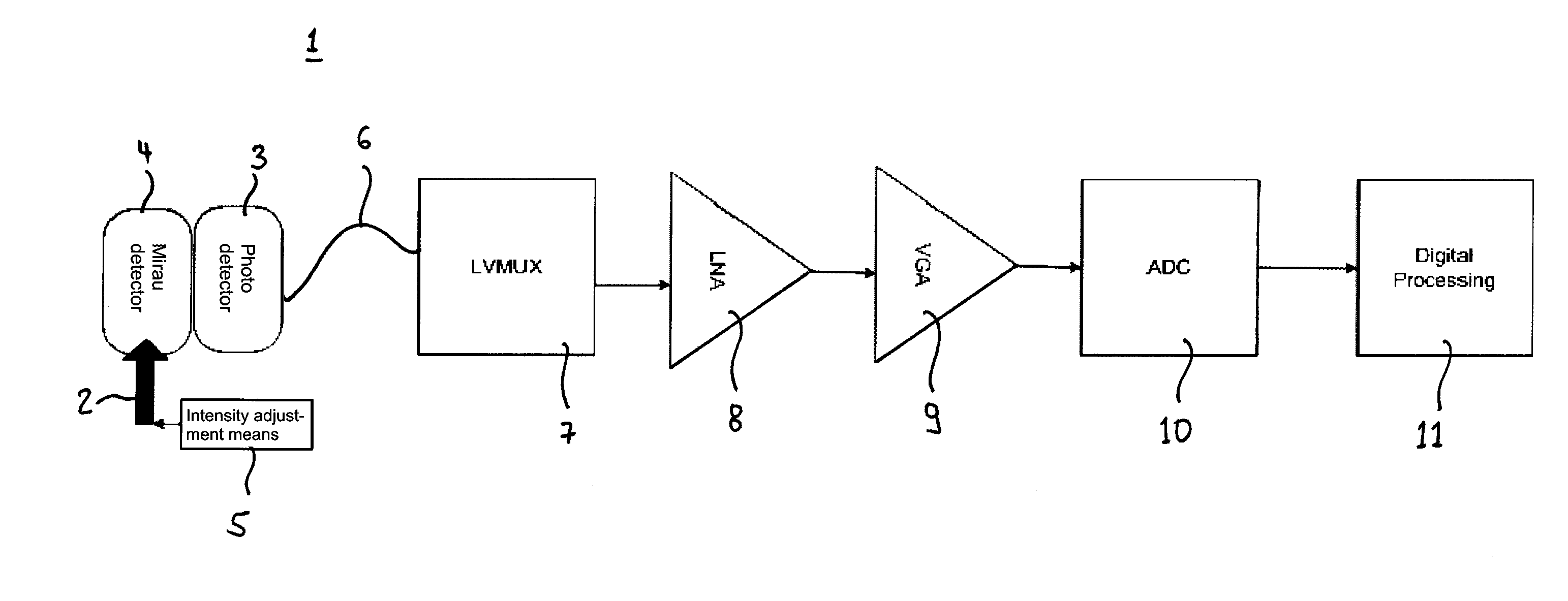
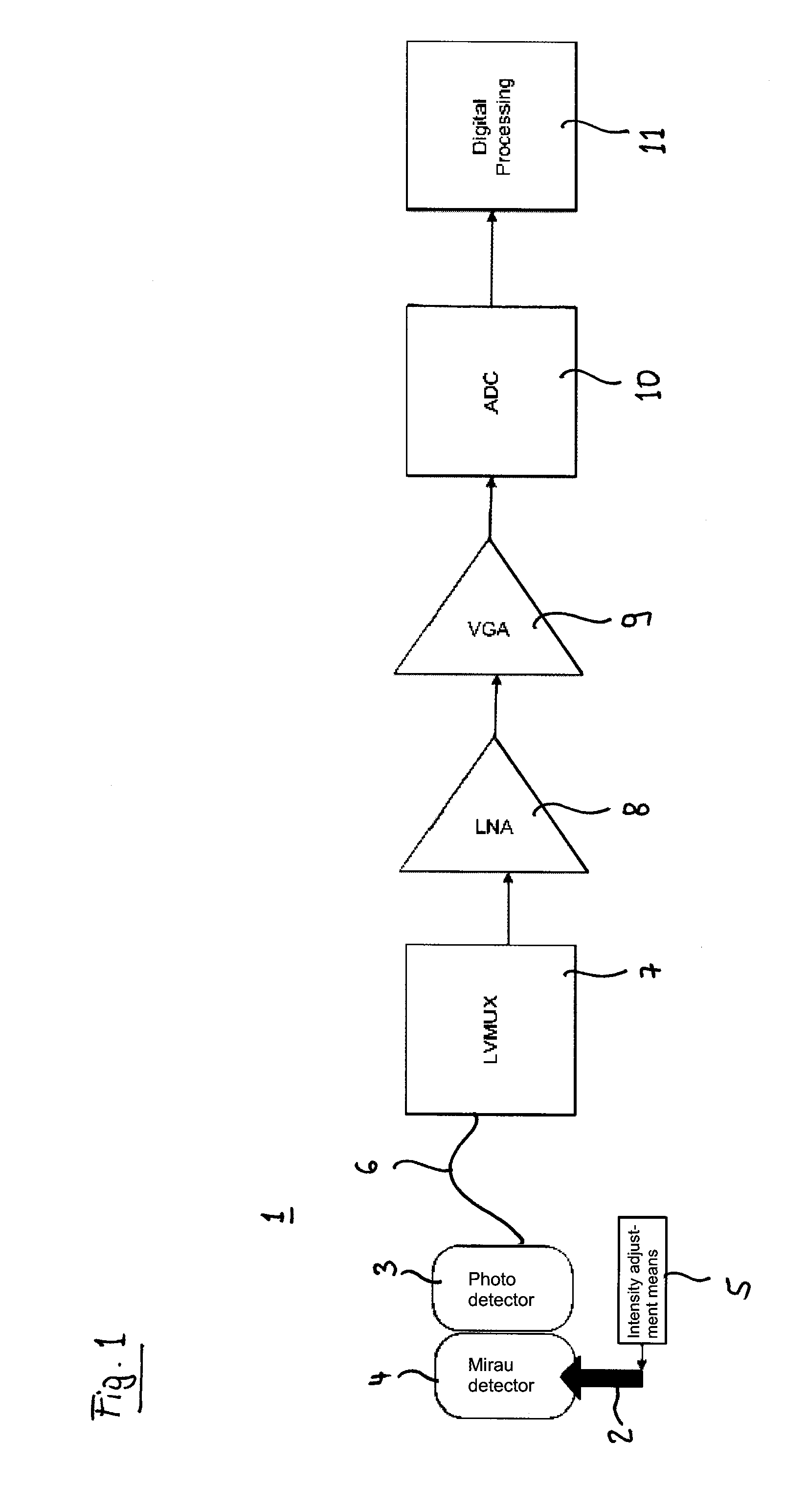
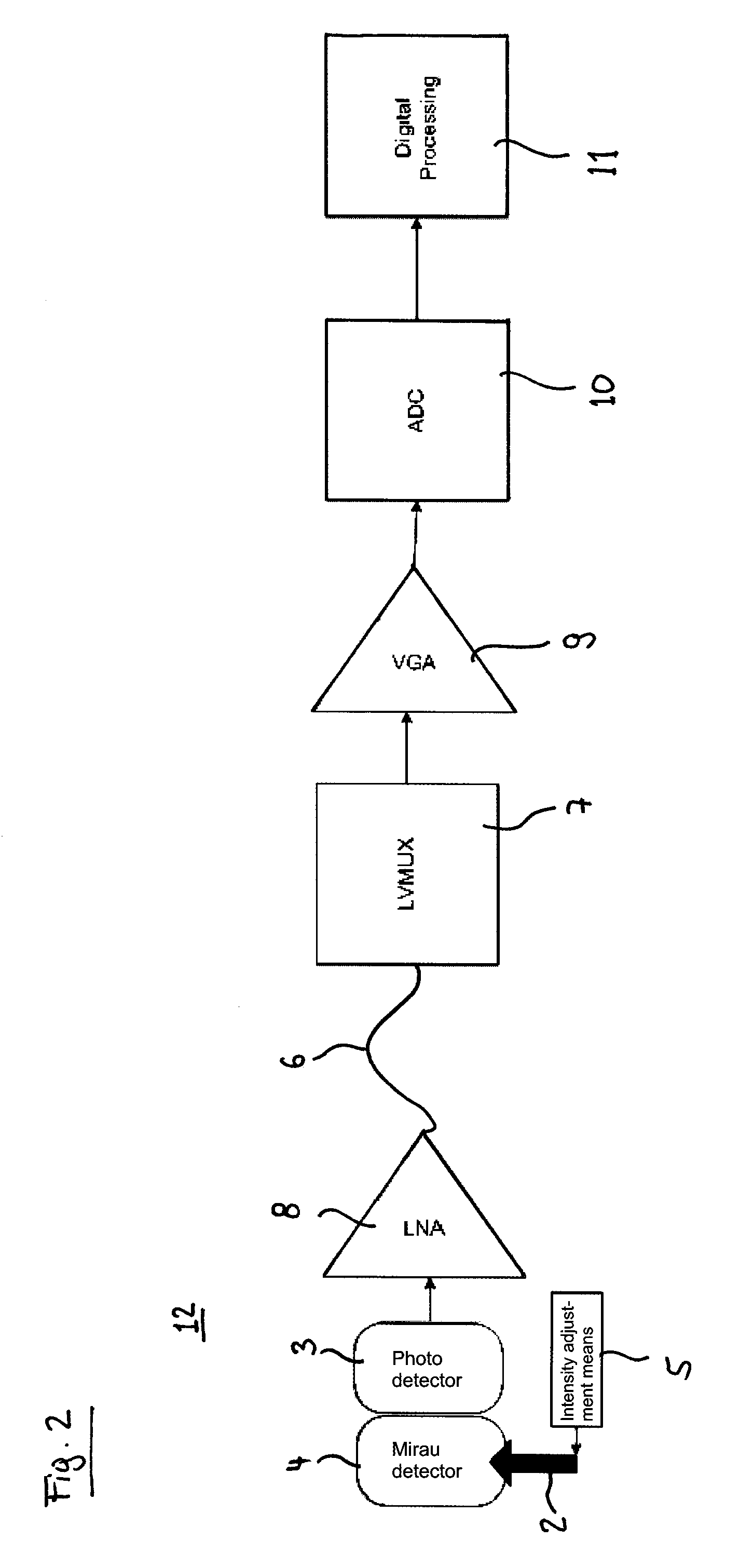
[0013]In a preferred embodiment of the invention, the intensity adjustment means control the light source in order to adjust the intensity of the light emitted by the light source. In particular for light sources, the intensity of which can easily be controlled, e.g. by adjusting a supply voltage or current, this is a simple and straight forward method of adjusting the intensity of the light incident on the photo detector. Alternatively, the intensity adjustment means may comprise an attenuation means located in the optical path from the light source to the photo detector via the optical ultrasound detector to attenuate the light. The attenuation means may e.g. be an aperture or a liquid crystal device or an electro-optical device such as a Pockels cell or even an integrated optical device such as an electro-optical modulator. Achievable advantages of using ...
PUM
 Abstract
Description
Claims
Application Information