Focus ring heating method, plasma etching apparatus, and plasma etching method

Active Publication Date: 2010-08-26
TOKYO ELECTRON LTD
View PDF7 Cites 29 Cited by
  • Summary
  • Abstract
  • Description
  • Claims
  • Application Information

AI Technical Summary

Benefits of technology

[0016]In accordance with the embodiments of the present invention, it is possible to provide a focus ring heating method and a plasma etching apparatus, in which members inside the vacuum chamber can be suppressed from being worn out without a dummy substrate and a structure of the heating mechanism can be simplified to suppress the increase of a manufacturing cost as compared with a conventional method.
[0017]In accordance with

Problems solved by technology

If a plasma is generated in the vacuum processing chamber while no dummy substrate is mounted, the surface of an electrostatic chuck may be damaged by the plasma, the electrostatic chuck being provided on the lower electrode to electrostatically attract the substrate.
However, if the plasma is generated in

Method used


Image

  • Focus ring heating method, plasma etching apparatus, and plasma etching method
  • Focus ring heating method, plasma etching apparatus, and plasma etching method
  • Focus ring heating method, plasma etching apparatus, and plasma etching method

Examples


first embodiment

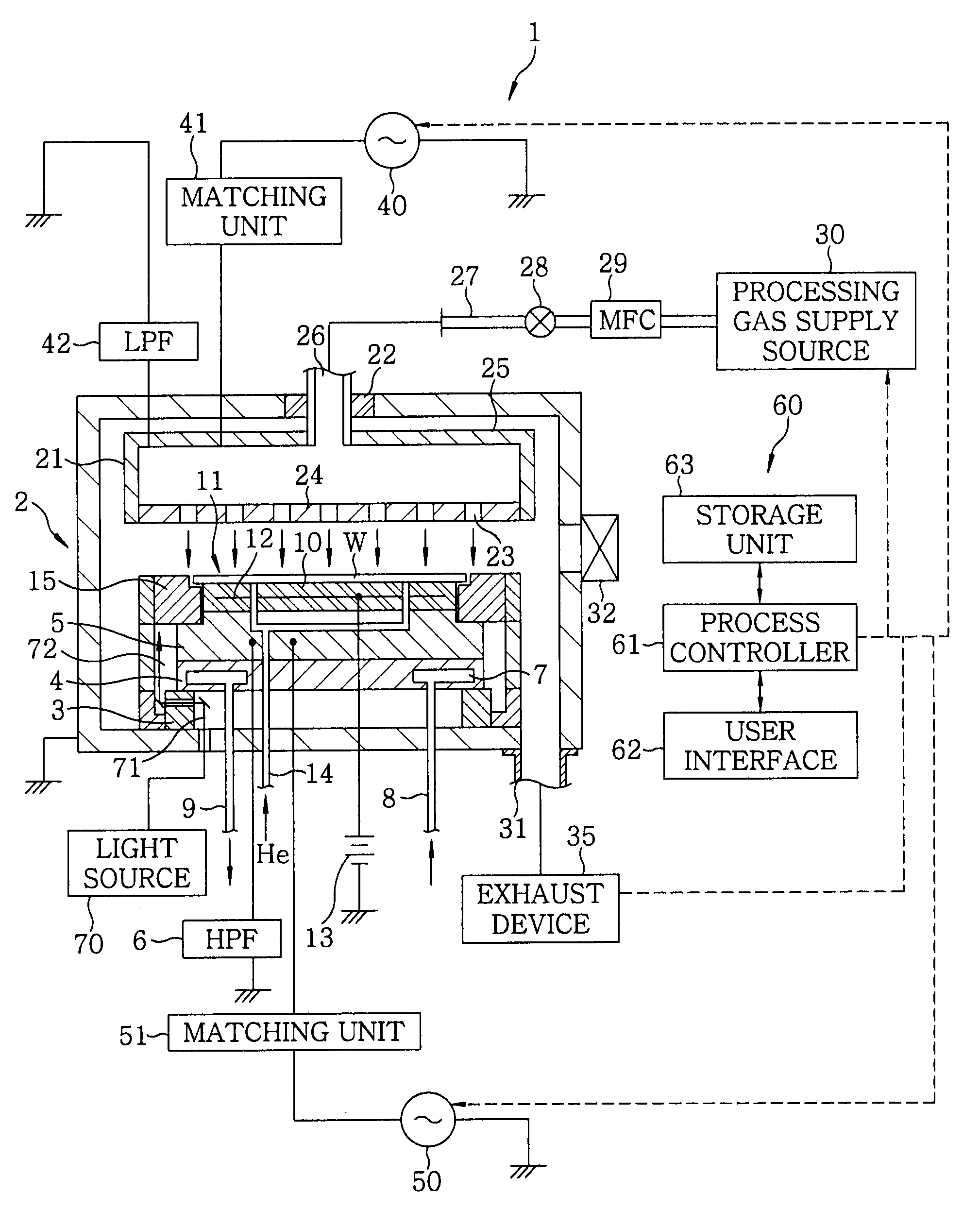
[0059]Embodiments of the present invention will now be described with reference to the accompanying drawings which form a part hereof. FIG. 1 is a cross sectional view schematically showing a structure of a plasma etching apparatus 1 in accordance with the present invention. First, the structure of the plasma etching apparatus 1 will be described with reference to FIG. 1.

[0060]The plasma etching apparatus 1 is a capacitively coupled parallel plate type etching apparatus in which electrode plates are respectively arranged at an upper and a lower portion to face each other in parallel and connected to a plasma generating power supply.

[0061]The plasma etching apparatus 1 includes a cylindrical vacuum processing chamber 2 made of, e.g., aluminum whose surface is anodically oxidized. The vacuum processing chamber 2 is grounded. At a bottom portion in the vacuum processing chamber 2, a substantially cylindrical susceptor support 4 for mounting thereon a target substrate, e.g., a semicondu...

second embodiment

[0114]FIG. 13 is a cross sectional view schematically showing a structure of a plasma etching apparatus 1a in accordance with the present invention.

[0115]The plasma etching apparatus 1a is a capacitively coupled parallel plate type etching apparatus in which electrode plates are respectively arranged at an upper and a lower portion to face each other in parallel and connected to a plasma generating power supply. Same reference numerals are given to components corresponding to those of the plasma etching apparatus 1 shown in FIG. 1 and the redundant description thereof will be omitted herein.

[0116]In the plasma etching apparatus 1a of the present embodiment, the ring-shaped focus ring 15 is arranged on an upper peripheral portion of the susceptor 5 to surround the semiconductor wafer W mounted on the electrostatic chuck 11. The focus ring 15 is made of, e.g., silicon, SiC or the like and serves to improve an in-plane uniformity of etching.

[0117]An annular member (cover ring) 16 is pr...


PUM

PropertyMeasurementUnit
Angleaaaaaaaaaa
Shapeaaaaaaaaaa
Transparencyaaaaaaaaaa

Abstract

There are provided a method of heating a focus ring and a plasma etching apparatus, capable of simplifying a structure of a heating mechanism without a dummy substrate. The plasma etching apparatus includes a vacuum processing chamber; a lower electrode serving as a mounting table for mounting a substrate thereon; an upper electrode provided to face the lower electrode; a gas supply unit for supplying a processing gas; a high frequency power supply for supplying a high frequency power to the lower electrode to generate a plasma of the processing gas; and a focus ring provided on the lower electrode to surround a periphery of the substrate. In the plasma etching apparatus, the focus ring is heated by irradiating a heating light thereto from a light source provided outside the vacuum processing chamber.

Description

FIELD OF THE INVENTION[0001]The present invention relates to a method for heating a focus ring provided in a plasma etching apparatus that etches a substrate such as a semiconductor wafer, a glass substrate for a liquid crystal display apparatus, and the like by using a plasma; a plasma etching apparatus; and a plasma etching method.BACKGROUND OF THE INVENTION[0002]In general, a plasma etching apparatus for etching a substrate such as a semiconductor wafer and a glass substrate for a liquid crystal display apparatus by using a plasma has been employed in a manufacturing process of semiconductor devices, or the like.[0003]The plasma etching apparatus is typically configured to include, e.g., a vacuum processing chamber; a lower electrode provided in the processing chamber, the lower electrode also serving as a mounting table on which a substrate is mounted; and an upper electrode provided to face the lower electrode. A high frequency power is supplied to the lower electrode to genera...

Claims


Application Information

Patent Timeline
IPC IPC(8): C23F1/00C23F1/08
CPCH01J37/32091H01J37/32522H05H1/24H01J2237/334H01J37/32642H01J37/32
Inventor KOSHIMIZU, CHISHIOYAMAWAKU, JUNMATSUDO, TATSUOSAITO, MASASHI
Owner TOKYO ELECTRON LTD
Why Eureka
Try Eureka