
Thermally activated high efficiency heat pump

a heat pump and high-efficiency technology, applied in the field of combined vapor compression and rankine cycle system, can solve the problems of reducing efficiency, affecting the efficiency of heat pumps, and affecting the efficiency of cooling systems, so as to improve performance characteristics and increase efficiency

Inactive Publication Date: 2010-09-02
CARRIER CORP
View PDF0 Cites 46 Cited by
  • Summary
  • Abstract
  • Description
  • Claims
  • Application Information

AI Technical Summary

Benefits of technology

[0005]Briefly, in accordance with one aspect of the invention, the combined vapor compression and Rankine cycle systems include a common suction accumulator, with liquid refrigerant being drawn therefrom for the Rankine cycle and refrigerant vapor being drawn therefrom for the vapor compression cycle, thereby resulting in increased efficiencies, due to removal of the non-efficient heat exchange zone from the evaporator, and improved performance characteristics at off-design conditions.
[0006]In accordance with another aspect of the invention, the vapor from the outlet of the expander is combined with the vapor from the outlet of the compressor, with the combined flow being circulated through the vapor compression cycle. The evaporator capacity is therefore enhanced, and the condenser (heating) capacity is increased, thereby benefiting the operation in the heating mode. Also, the mass flow rate pumped by the compressor is less than the mass flow rate circulated through the evaporator, thereby reducing the ratio of the compressor power to the evaporator capacity. Further, when the ambient temperature decreases, in heating, liquid refrigerant density at the pump inlet, the mass flow rate through the Rankine loop, and the available power for the compressor, increase, thereby improving heating efficiency.
[0007]In accordance with another aspect of the invention, the liquid refrigerant in the suction accumulator has elevated concentrations of oil. This provides boiling point elevation, which is equivalent to a few degrees of subcooling and mitigates a risk associated with the cavitation phenomenon in the liquid refrigerant pump.
[0008]In accordance with another aspect of the invention, the outdoor and indoor heat exchangers are sized so as to provide non-complete evaporation, thereby eliminating the otherwise non-efficient vapor-to-air heat exchange zone, carrying a portion of liquid refrigerant enriched with compressor lubricant from the evaporator and moves it into the heat exchanger where the heat regeneration is accomplished more efficiently. Further, the pumped liquid has a higher specific heat at the boiling pressure then the condensed liquid at the condensing pressure, which provides heat regeneration of the non-evaporated portion and higher evaporator capacity. As a result, the cooling capacity and COP, and the heating capacity and COP, are higher. The non-evaporated liquid is the working fluid for the Rankine circuit, and the cooler liquid has a greater thermodynamic potential to cool the fluid carrying the thermal source for the boiler, thereby resulting in a higher thermodynamic efficiency of the power generation.
[0009]In accordance with another aspect of the invention, the inventive system may utilize trans-critical refrigerants and BZT-fluids which may be optimized to provide a better pump-to-expander power ratio.

Problems solved by technology

However, such heat pumps are very sensitive to ambient temperature in a heating mode of operation, since the heating capacity decreases as ambient temperature decreases.
Also, system operation in cooling is somewhat inefficient, and the efficiency drops when the ambient temperature increases.
Further, the combined systems cannot use trans-critical refrigerants, since there is no condensed liquid available downstream of the gas cooler for pumping through the Rankine circuit.

Method used


Image

  • Thermally activated high efficiency heat pump
  • Thermally activated high efficiency heat pump
  • Thermally activated high efficiency heat pump

Examples


Embodiment Construction

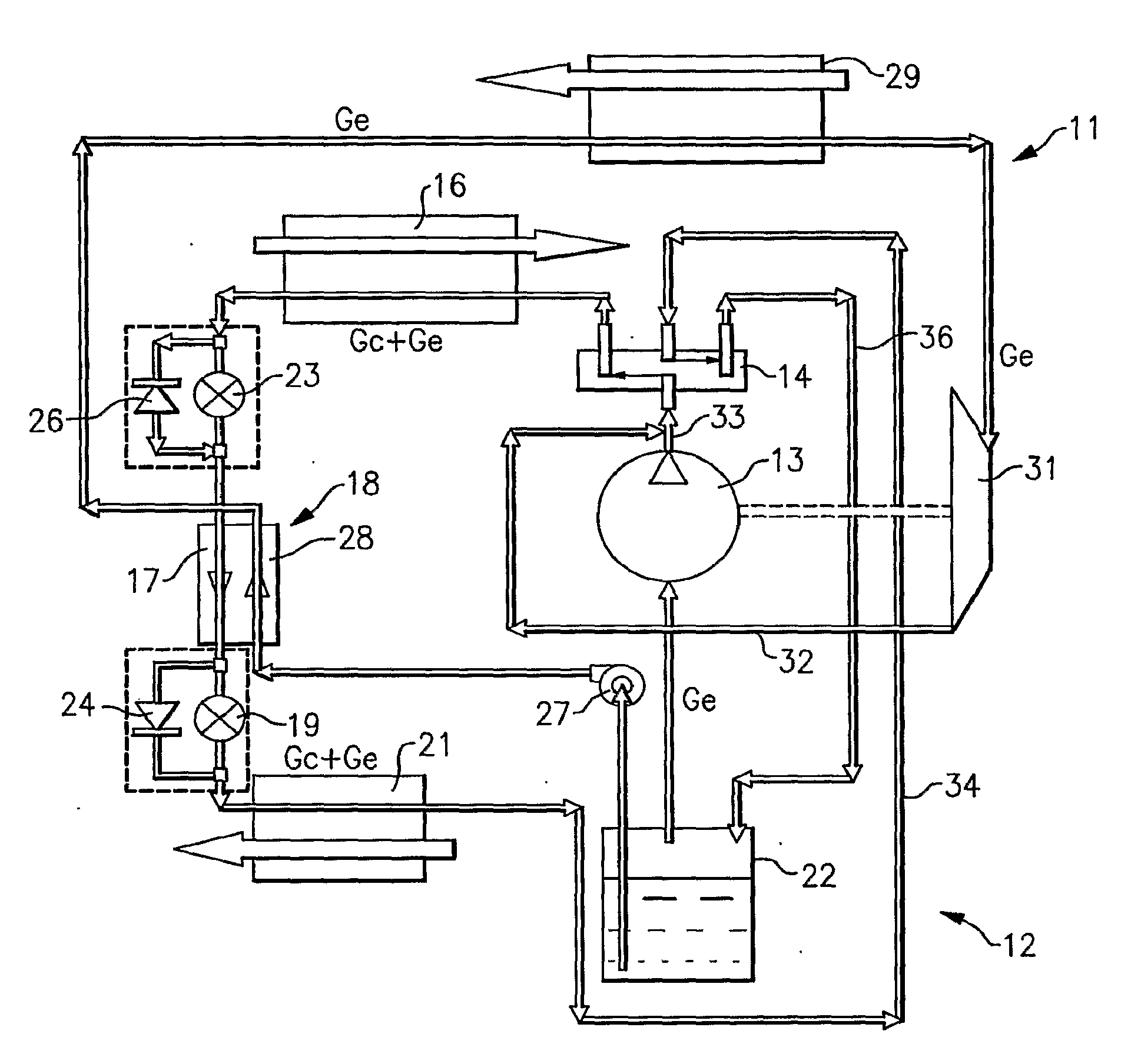
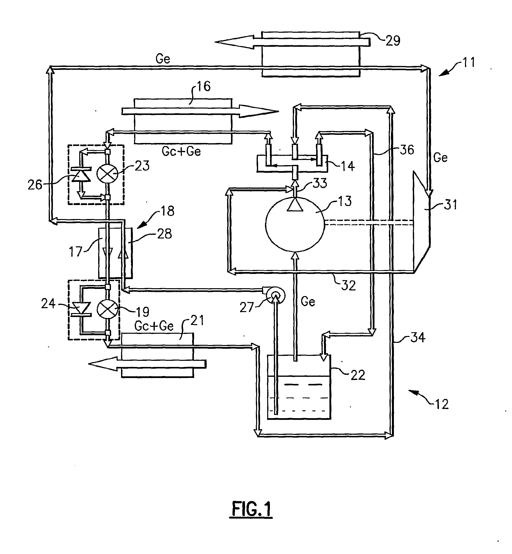
[0022]Shown in FIG. 1 is a system which, in accordance with the present invention, utilizes a combination of a Rankine and a vapor compression cycles. The cycle combination may be called a vapor compression and expansion cycle. The combined system may be called a vapor compression and expansion system.

[0023]The vapor compression circuit 12 includes, in serial flow communication relationship, a compressor 13, a reversing valve 14, an outdoor heat exchanger 16, one side (or a first pass) 17 of an economizer heat exchanger 18, an expansion device 19, an indoor heat exchanger 21, and a suction accumulator 22. Also, included is an expansion device 23 for use in the heating mode of operation. Bypass valves 24 and 26 may be provided to bypass the respective expansion devices 19 and 23 when switching between cooling and heating modes of operation. The reversing valve 14 is, of course, selectively controlled to operate in either the cooling or heating mode of operation.

[0024]The Rankine cycl...


PUM


Abstract

A vapor compression cycle system is combined with a Rankine cycle system, with the two systems having a common suction accumulator from which the compressor draws refrigerant vapor for the vapor compression cycle system and from which a pump draws liquid refrigerant for circulation within the Rankine cycle system. The vapor from the Rankine cycle system expander is passed to the compressor discharge to provide a mixture which is circulated within the vapor compression cycle system to obtain improved performance. The heat exchangers are sized so as to obtain a non-complete evaporation, with the resulting two-phase fluid passing to the suction accumulator to provide liquid refrigerant to the Rankine cycle system and vapor refrigerant to the vapor compression cycle system.

Description

TECHNICAL FIELD[0001]This invention relates generally to vapor compression systems and, more particularly, to a combined vapor compression and a Rankine cycle system.BACKGROUND OF THE INVENTION[0002]It is known to combine a vapor compression system with a Rankine cycle system. See, for example, U.S. Pat. No. 6,962,056, assigned to the assignee of the present invention. In the U.S. Pat. No. 5,761,921 power generated in the Rankine cycle is applied to drive the compressor of the vapor compression cycle, and the combined systems operate on three pressure levels, i.e. the boiler, condenser and evaporator pressure levels.[0003]In the U.S. Pat. No. 5,761,921, the condenser (heating) capacity includes two main components, the boiler heat exchanger capacity and the evaporator capacity, thereby increasing the heating effect for a given thermal input. However, such heat pumps are very sensitive to ambient temperature in a heating mode of operation, since the heating capacity decreases as ambi...

Claims


Application Information

Patent Timeline
IPC IPC(8): F25B9/14F25B43/02F25B41/00F25B7/00F25B27/00F25B1/00
CPCF01K7/32F01K7/34F01K17/005Y02E20/14F25B27/00F25B2309/061F25B2400/23F01K25/06
Inventor VAISMAN, IGOR B.TARAS, MICHAEL F.SANGIOVANNI, JOSEPH J.
Owner CARRIER CORP
Features
  • Generate Ideas
  • Intellectual Property
  • Life Sciences
  • Materials
  • Tech Scout
  • Unparalleled Data Quality
  • Higher Quality Content
  • 60% Fewer Hallucinations
Learn More