Comppsite film for superstrate solar cell, method for producing the composite film for superstrate solar cell, composite film for substrate solar cell, and method for porducing the composite film for substrate solar cell

a solar cell and composite film technology, applied in the field of composite films, can solve the problems of large amount of time and energy, difficult to improve the mass productivity, and complex subsequent production process steps, etc., and achieve satisfactory reflectance, increase reflection effect, and production comparatively cheap

Inactive Publication Date: 2010-09-02
MITSUBISHI MATERIALS CORP
View PDF6 Cites 26 Cited by
  • Summary
  • Abstract
  • Description
  • Claims
  • Application Information

AI Technical Summary

Benefits of technology

[0123]The composite film for a superstrate thin-film solar cell according to the first aspect of the present invention has two layers composed of a transparent conductive film formed on a photovoltaic layer of the superstrate thin-film solar cell, and a conductive reflective film formed on top of the transparent conductive film, wherein the transparent conductive film is formed by using a wet coating method to apply a transparent conductive film composition containing conductive oxide microparticles, and the conductive reflective film is formed by using a wet coating method to apply a conductive reflective film composition containing metal nanoparticles. As a result, the transparent conductive film is formed with a lower refractive index than that of a transparent conductive film formed using a vacuum deposition method such as sputtering, meaning an increased reflection effect is achieved at the conductive reflective film, and a satisfactory reflectance can be obtained. Furthermore, the average diameter of holes occurring at the substrate-side contact surface of the conductive reflective film is not more than 100 nm, the average depth at which the holes are positioned is not more than 100 nm, and the number density of the holes is not more than 30 holes/μm2. As a result, when a transparent substrate having a transmittance of at least 98% is used, a high diffuse reflectance equivalent to not less than 80% of the theoretical reflectance can be achieved within a wavelength range from 500 to 1,200 nm.
[0124]Furthermore, by eliminating vacuum processes such as vacuum deposition and sputtering as far as possible, and using a wet coating method, the composite film can be produced comparatively cheaply.
[0125]The composite film for a superstrate solar cell according to the second aspect of the present invention has a transparent conductive film formed on a photovoltaic layer of a superstrate thin-film solar cell, and a conductive reflective film formed on top of the transparent conductive film, wherein the transparent conductive film is formed by forming a coating of conductive oxide microparticles by using a wet coating method to apply a dispersion of the conductive oxide microparticles to the photovoltaic layer, impregnating the coating of the conductive oxide microparticles with a binder dispersion using a wet coati

Problems solved by technology

However, large amounts of time and energy are required to grow the silicon crystals used in these bulk solar cells, and the subsequent production process also requires complex steps.
As a result, improving the mass productivity is difficult, and providing low-cost solar cells has proven problematic.
Particularly in those cases where the photovoltaic layer is formed of a silicon-based material, because the absorption coefficient for the photovoltaic layer is comparatively small, if the photovoltaic layer is formed with a thickness in the order of several micrometers, then a portion of the incident light passes through the photovoltaic layer, and this transmitted light is unable to contr

Method used


Image

  • Comppsite film for superstrate solar cell, method for producing the composite film for superstrate solar cell, composite film for substrate solar cell, and method for porducing the composite film for substrate solar cell
  • Comppsite film for superstrate solar cell, method for producing the composite film for superstrate solar cell, composite film for substrate solar cell, and method for porducing the composite film for substrate solar cell
  • Comppsite film for superstrate solar cell, method for producing the composite film for superstrate solar cell, composite film for substrate solar cell, and method for porducing the composite film for substrate solar cell

Examples


first embodiment

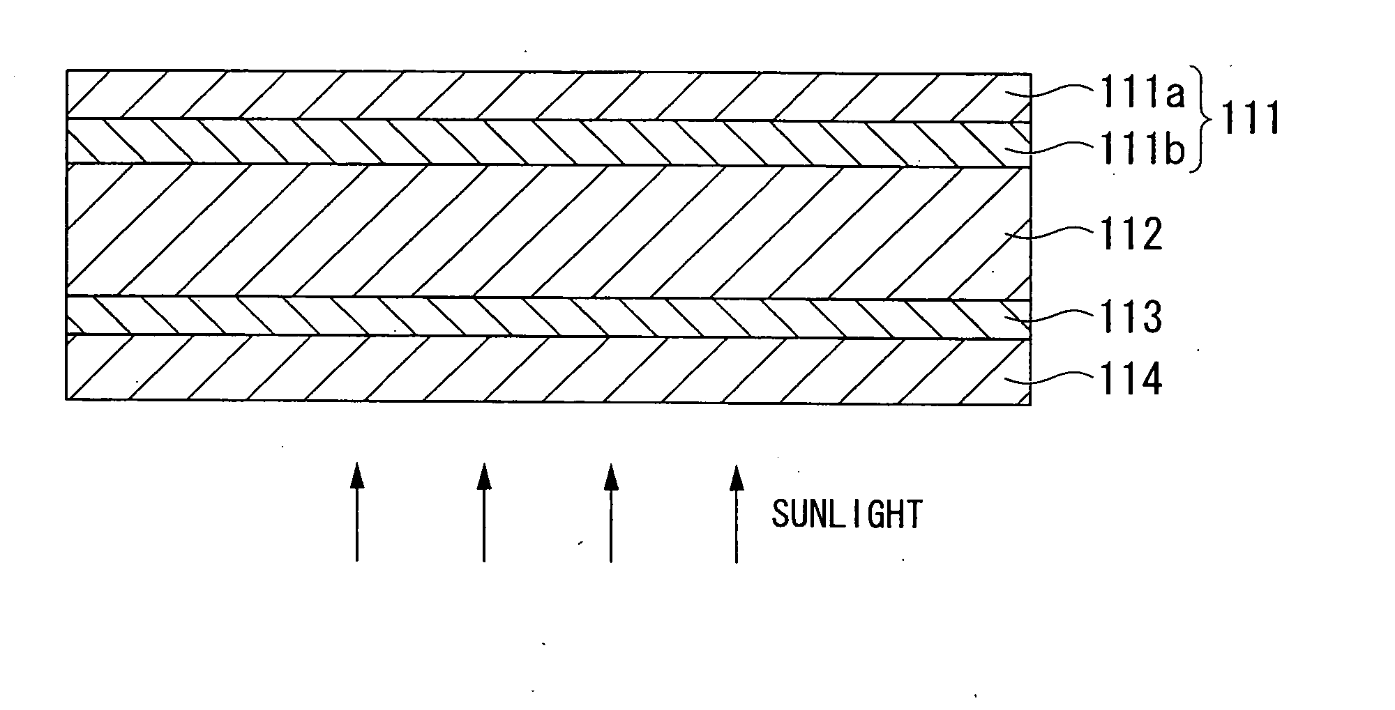
[0170]As illustrated in FIG. 1, a superstrate thin-film solar cell typically has a structure in which a first transparent conductive film (the light incident side transparent conductive film) 113 and a photovoltaic layer 112 are laminated sequentially on top of a substrate 114, a second transparent conductive film 111b is formed on top of the photovoltaic layer 112, and a conductive reflective film 111a is then formed on top of the second transparent conductive film 111b.

[0171]The first embodiment of the present invention relates to a composite film 111 for a superstrate thin-film solar cell that is composed of two layers, namely, the second transparent conductive film 111b formed on top of the photovoltaic layer 112, and the conductive reflective film 111a formed on top of the second transparent conductive film 111b.

[0172]In the composite film 111 according to the first embodiment of the present invention, the second transparent conductive film 111b is formed by using a wet coati...

second embodiment

[0216]A superstrate thin-film solar cell generally has a structure in which a first transparent conductive film (the light incident side transparent conductive film) and a photovoltaic layer are laminated sequentially on top of a substrate, a second transparent conductive film is formed on top of the photovoltaic layer, and a conductive reflective film is then formed on top of the second transparent conductive film.

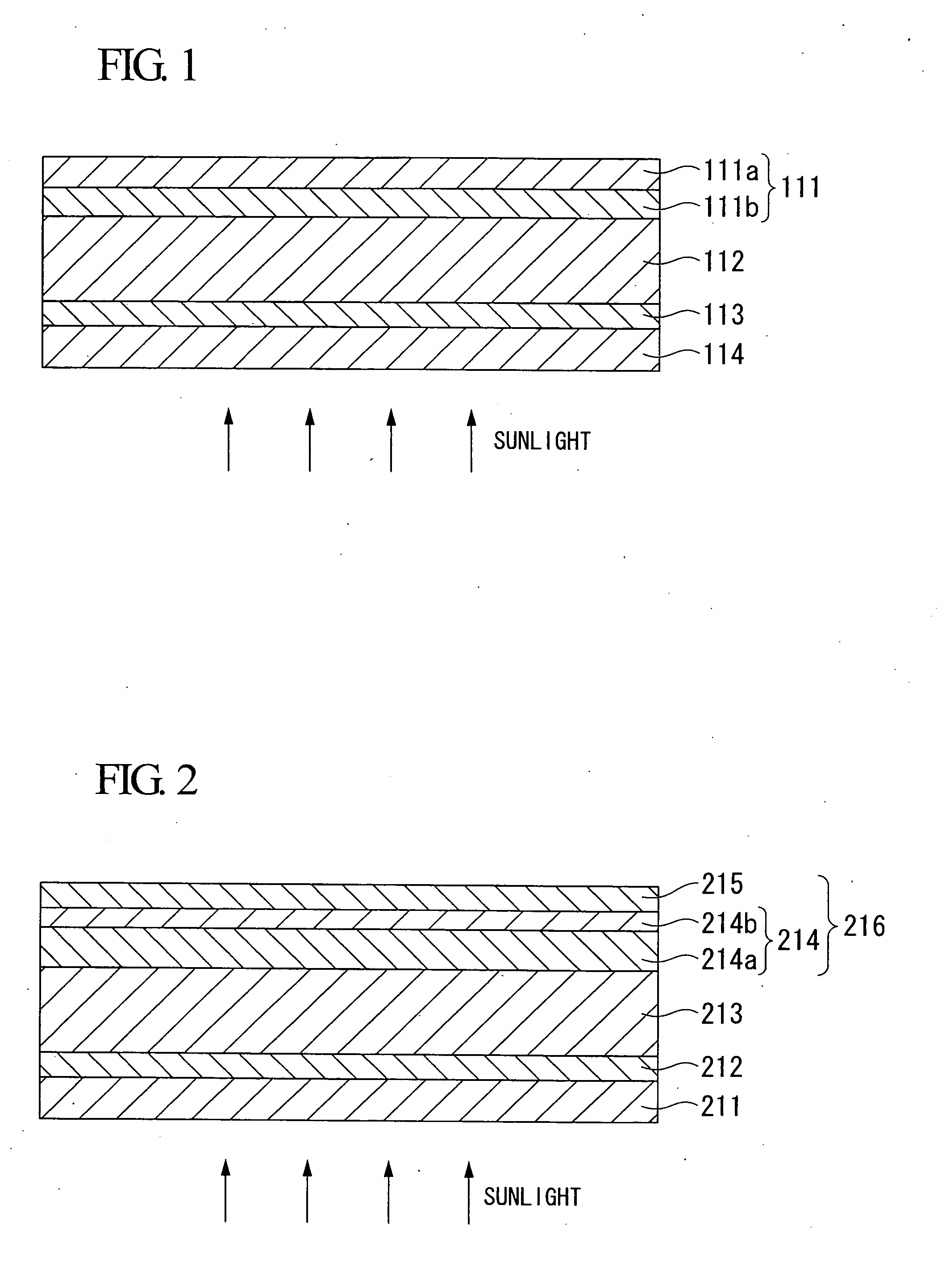
[0217]The second embodiment of the present invention relates to a composite film for a superstrate solar cell having a second transparent conductive film formed on a photovoltaic layer of the superstrate solar cell, and a conductive reflective film formed on top of the second transparent conductive film.

[0218]FIG. 2 is a diagram that schematically illustrates a cross-section of the composite film according to the second embodiment of the present invention. As illustrated in FIG. 2, the special features of the structure of the composite film 216 of the second embodiment of...

third embodiment

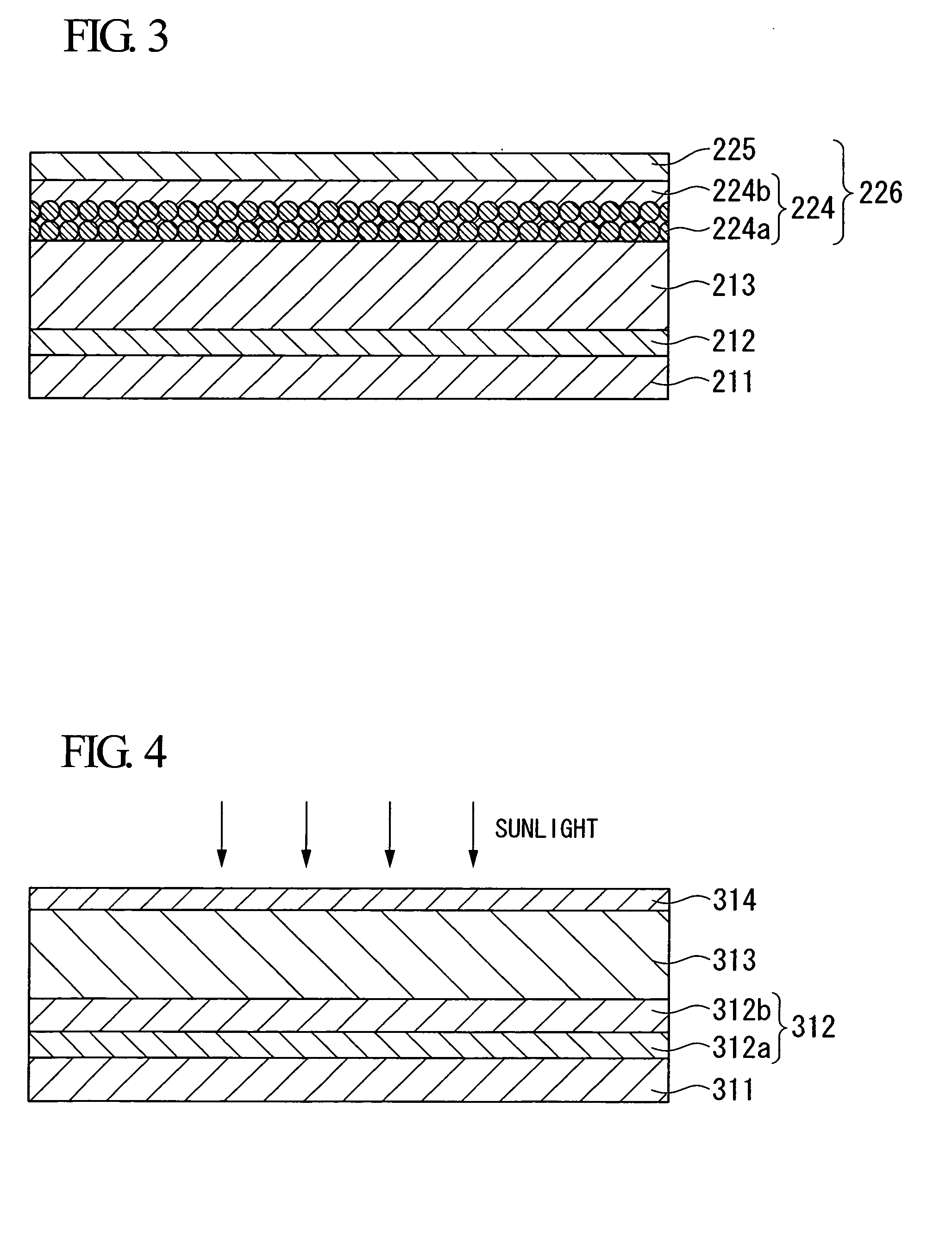
[0267]As illustrated in FIG. 4, a substrate thin-film solar cell typically has a structure in which a composite film 312 is formed on top of a substrate 311, and a photovoltaic layer 313 and a first transparent conductive film (the light incident side transparent conductive film) 314 are laminated sequentially on top of the composite film 312. The composite film 312 includes a conductive reflective film 312a formed on the substrate 311 and a second transparent conductive film 312b formed on the conductive reflective film 312a.

[0268]The third embodiment of the present invention relates to a composite film 312 for a substrate solar cell that is composed of two layers, namely, the conductive reflective film 312a formed on the substrate 311 and the second transparent conductive film 312b formed on the conductive reflective film 312a.

[0269]In the composite film 312 of the third embodiment of the present invention, the conductive reflective film 312a is formed by using a wet coating met...


PUM


Abstract

A composite film for a superstrate solar cell or a substrate solar cell has a transparent conductive film and a conductive reflective film, wherein the transparent conductive film is formed by using a wet coating method to apply a transparent conductive film composition or dispersion containing microparticles of a conductive oxide, the conductive reflective film is formed by using a wet coating method to apply a conductive reflective film composition containing metal nanoparticles, the average diameter of holes occurring at the contact surface of the conductive reflective film on either the side of the photovoltaic layer or the side of the transparent conductive film is not more than 100 nm, the average depth at which the holes are positioned is not more than 100 nm, and the number density of the holes is not more than 30 holes/μm2.

Description

TECHNICAL FIELD[0001]The present invention relates to a composite film having two layers, namely a transparent conductive film and a conductive reflective film, and also to a method for producing such a composite film. More specifically, the present invention relates to a composite film that is ideal for use within a superstrate thin-film solar cell or substrate solar cell, and a method for producing such a composite film.[0002]This application claims priority on Japanese Patent Application No. 2007-236546, filed on Sep. 12, 2007, Japanese Patent Application No. 2008-205849, filed on Aug. 8, 2008, Japanese Patent Application No. 2008-205862, filed on Aug. 8, 2008, Japanese Patent Application No. 2008-205867, filed on Aug. 8, 2008, Japanese Patent Application No. 2008-205870, filed on Aug. 8, 2008, Japanese Patent Application No. 2008-224497, filed on Sep. 2, 2008, Japanese Patent Application No. 2008-224499, filed on Sep. 2, 2008, Japanese Patent Application No. 2008-224508, filed o...

Claims


Application Information

Patent Timeline
IPC IPC(8): H01L31/0256B05D5/12
CPCH01L31/03921Y02E10/52H01L31/056H01L31/02366H01L31/052H01L31/02168H01L31/022466H01L31/022475H01L31/022483H01L31/1884
Inventor YAMASAKI, KAZUHIKOHAYASHI, TOSHIHARUARAI, MASAHIDEOGAWA, SATOKOTAKATA, YOSHIAKI
Owner MITSUBISHI MATERIALS CORP
Why Eureka
Try Eureka