Linearly polarized backlight source in conjunction with polarized phosphor emission screens for use in liquid crystal displays

a backlight source and phosphor technology, applied in the direction of luminescent compositions, instruments, semiconductor devices, etc., can solve the problems of usable light, and achieve the effect of improving the efficiency of the present invention's system, reducing the efficiency of lcd, and reducing usable ligh

Inactive Publication Date: 2010-09-02
RGT UNIV OF CALIFORNIA
View PDF10 Cites 246 Cited by
  • Summary
  • Abstract
  • Description
  • Claims
  • Application Information

AI Technical Summary

Benefits of technology

[0024]The use of polarized phosphors in the display will eliminate the need for color filters which decrease the efficiency of the LCD due to the decrease in usable light. Since a polarized light source (such as semipolar or nonpolar (Ga, Al, In, B)N) can be used, the need for two polarizers is reduced to one, thereby further improving the efficiency of the present invention's system.
[0025]Although the results were performed on YAG:Ce, the present invention is equally applicable to Y3(Al, Ga)5O12:(Tb, Gd, Eu, Er and other rare earth ions) as well as other red, green, and blue emitting phosphors which show polarization anisotropy when excited. The term phosphor used herein refers to a material that exhibits photoluminescence which is the process of a substance absorbing a photon and then re-radiating the photon at a lower energy. Quantum mechanically, it is the process where an electron is excited to a higher energy state and then returns to the lower energy state accompanied by the emission of a photon. When using a phosphor with polarization properties for LCD backlighting applications, a system to selectively pick which polarization state is needed without the extra polarizer is enabled, thereby making the system more compact and efficient.

Problems solved by technology

The use of polarized phosphors in the display will eliminate the need for color filters which decrease the efficiency of the LCD due to the decrease in usable light.

Method used


Image

  • Linearly polarized backlight source in conjunction with polarized phosphor emission screens for use in liquid crystal displays
  • Linearly polarized backlight source in conjunction with polarized phosphor emission screens for use in liquid crystal displays
  • Linearly polarized backlight source in conjunction with polarized phosphor emission screens for use in liquid crystal displays

Examples


Embodiment Construction

[0040]In the following description of the preferred embodiment, reference is made to the accompanying drawings which form a part hereof, and in which is shown by way of illustration a specific embodiment in which the invention may be practiced. It is to be understood that other embodiments may be utilized and structural changes may be made without departing from the scope of the present invention.

[0041]Overview

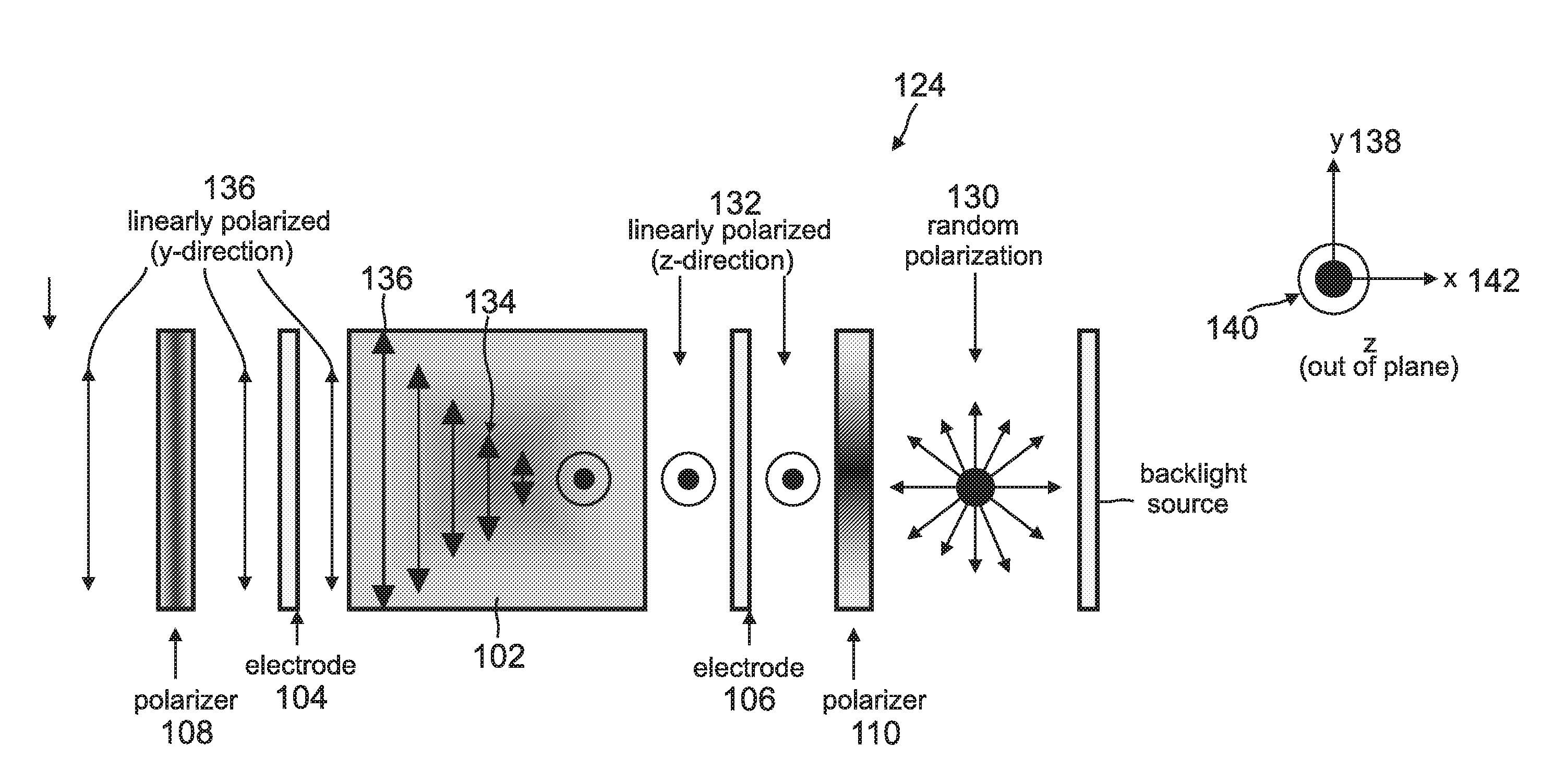
[0042]The inventors performed an experiment showing that phosphor powder was only very slightly polarized. However, the inventors also performed an experiment showing the down-converted emission of a cubic single crystal (YAG:Ce3+) was 100% polarized when excited by linearly polarized light, illustrating that single crystal phosphors are beneficial in LCDs. Consequently, a single crystal phosphor can be used to fabricate an efficient LCD that eliminates one polarizer and color filters and utilizes the polarizing nature of the phosphor in conjunction with a polarizing source su...


PUM

PropertyMeasurementUnit
wavelengthsaaaaaaaaaa
luminescentaaaaaaaaaa
OPTICAL POLARIZATIONaaaaaaaaaa

Abstract

A device for displaying images positions a luminescent material between a light source and a liquid crystal display (LCD). The light source, which comprises one or more nonpolar or semipolar III-nitride based light emitting diodes (LEDs), emits a primary light having a specified polarization direction and comprising one or more first wavelengths. This primary light emitted by the light source is a linearly polarized light that eliminates any need for a polarizer. The luminescent material, which comprises one or more phosphors, is optically pumped by the primary light and emits a secondary light having the polarization direction of the primary light, wherein the secondary light is comprised one or more second wavelengths that are different from the first wavelength. This secondary light emitted by the luminescent material is a colored light that eliminates any need for a color filter. The LCD receives the secondary light and displays one or more images in response thereto.

Description

CROSS REFERENCE TO RELATED APPLICATIONS[0001]This application claims the benefit under 35 U.S.C. Section 119(e) of co-pending and commonly-assigned:[0002]U.S. Provisional Application Ser. No. 61 / 086,431 filed on Aug. 5, 2008, by Natalie N. Fellows, Steven P. DenBaars, and Shuji Nakamura, entitled “LINEARLY POLARIZED BACKLIGHT SOURCE IN CONJUNCTION WITH POLARIZED PHOSPHOR EMISSION SCREENS FOR USE IN LIQUID CRYSTAL DISPLAYS,” attorney's docket number 30794.282-US-P1 (2008-802),[0003]which application is incorporated by reference herein.[0004]This application is related to the following co-pending and commonly-assigned U.S. patent applications:[0005]U.S. Utility application Ser. No. 12 / 272,588, filed on Nov. 17, 2008, by Hisashi Masui, Shuji Nakamura and Steven P. DenBaars, entitled “PACKAGING TECHNIQUE FOR THE FABRICATION OF POLARIZED LIGHT EMITTING DIODES,” attorneys' docket number 30794.139-US-U1 (2005-614-2), which application is a continuation of and claims the benefit under 35 U....

Claims


Application Information

Patent Timeline
Patent Type & Authority Applications(United States)
IPC IPC(8): G02F1/1335H01L33/44C09K11/80
CPCG02F1/13362G02F1/133617G02F1/1335
Inventor DEMILLE, NATALIE FELLOWSDENBAARS, STEVEN P.NAKAMURA, SHUJI
Owner RGT UNIV OF CALIFORNIA
Why Eureka
Try Eureka