Infrared furnace system

a furnace system and infrared technology, applied in the direction of furnaces, drying machines with progressive movements, lighting and heating apparatus, etc., can solve the problems of providing a process with only one rate of wafer passing speed and the way, and achieve the effect of optimizing the heating and/or cooling profile and minimizing the footprin

Inactive Publication Date: 2010-09-02
BTU INTERNATIONAL
View PDF18 Cites 31 Cited by
  • Summary
  • Abstract
  • Description
  • Claims
  • Application Information

AI Technical Summary

Benefits of technology

[0007]In one embodiment of the present invention, an infrared furnace system includes multiple sections, e.g., drying, burnout/firing, and cooling, each having a separate conveyor belt so that a workpiece may travel through a respective section at a rate that is different from the rate at which the workpiece may pass through any other section. Advantageously, the present infrared furn

Problems solved by technology

A furnace with only a single conveyor belt running through its entire length, however, provides a process that has only one rate of speed for passing the wafers through the system.
Providing a second belt, however, p

Method used


Image

  • Infrared furnace system
  • Infrared furnace system
  • Infrared furnace system

Examples


Embodiment Construction

[0036]The entire contents of U.S. Provisional Patent Application Ser. No. 61 / 156,588 for “Infrared Furnace System,” filed Mar. 2, 2009, is incorporated by reference herein for all purposes.

[0037]In the following detailed description, numerous specific details are set forth in order to provide a thorough understanding of the embodiments of the present invention. It will be understood by those of ordinary skill in the art that these embodiments of the present invention may be practiced without some of these specific details. In other instances, well-known methods, procedures, components and structures may not have been described in detail so as not to obscure the embodiments of the present invention.

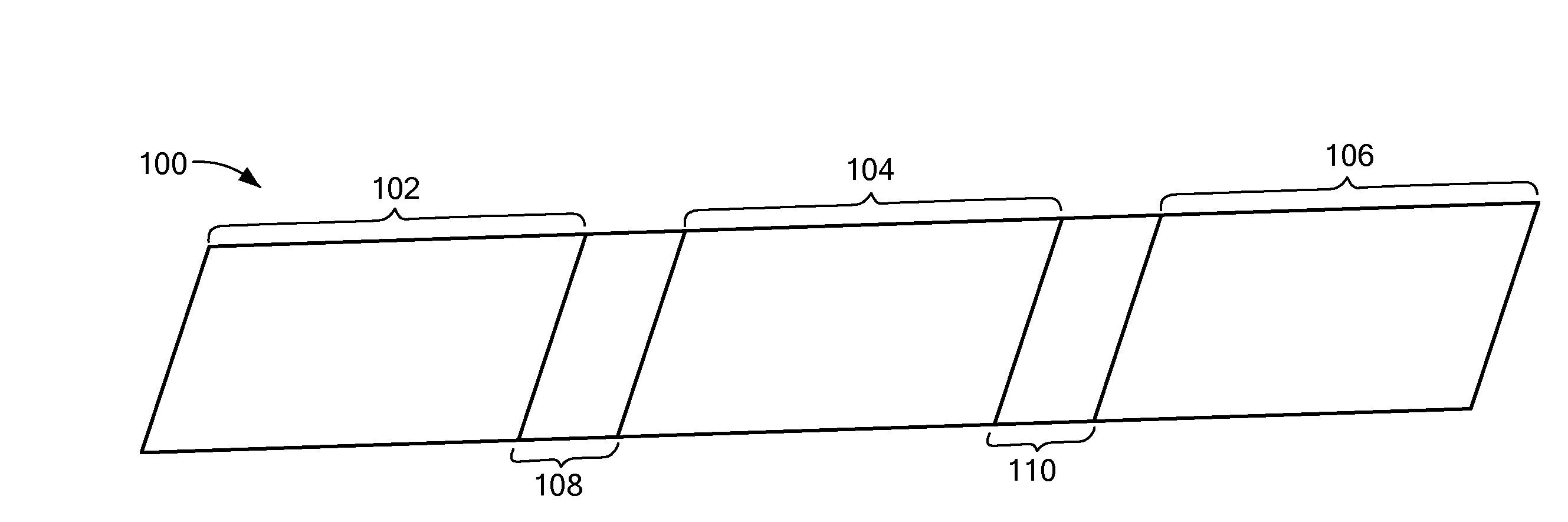
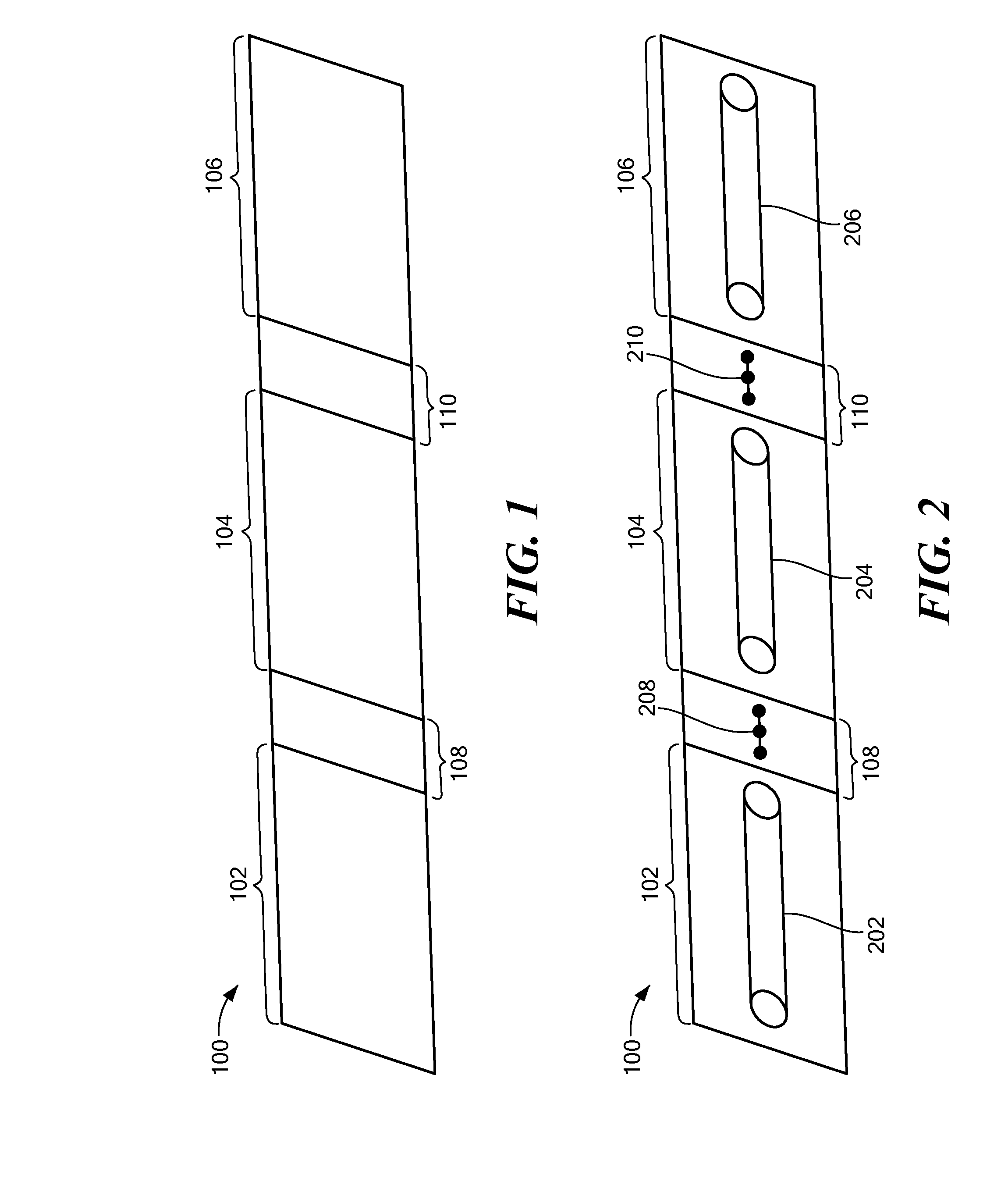
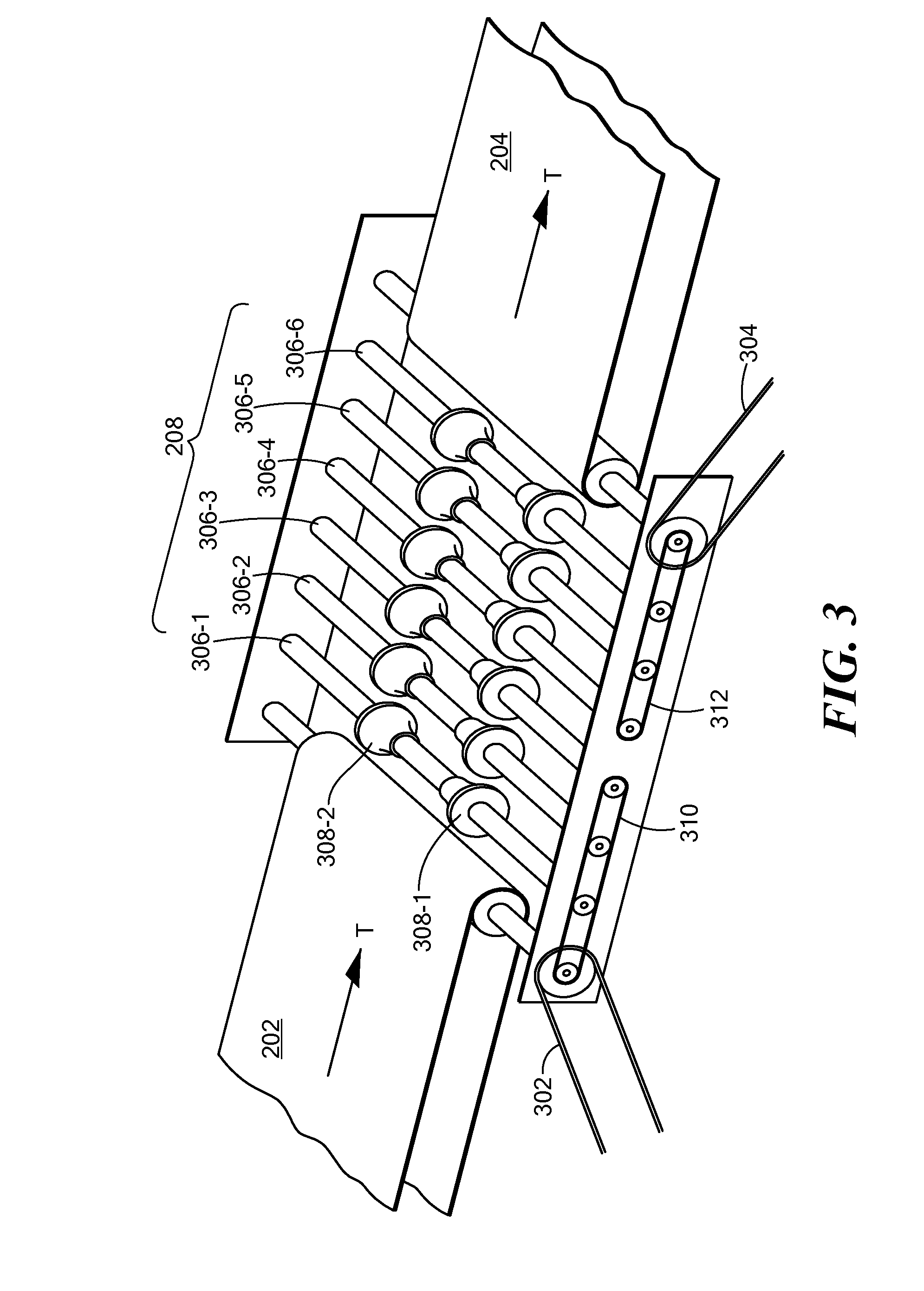
[0038]As will be described in more detail below, an infrared furnace system, in accordance with various embodiments of the present invention, provides a system that allows for adjusting the amount of time a wafer spends in a respective section of the furnace while at the same time minimizi...


PUM


Abstract

An infrared furnace system provides for adjusting the amount of time a workpiece spends in a respective section of the furnace while at the same time minimizing the footprint, i.e., the amount of floor space that the furnace uses. Various embodiments allow for optimizing the required thermal duration of each section which then also optimizes the heating and/or cooling profile within each section. Transfer conveyors are provided to transfer a workpiece from one conveyor operating at a first speed to a second conveyor operating at a second speed, different from the first speed in order to prevent damage to the workpiece. Rollers are provided to support the workpiece and to maintain a proper orientation. A heating lamp support assembly provides power to the lamp and facilitates exchange and replacement of the lamp. An air delivery system provides process gas maintained at the correct temperature. An exhaust system provides air flow with improved turnover and reduced noise considerations. Infrared heating lamps are cooled by providing gas flow across the end terminals. The wavelength of light emitted by the heating lamps is adjusting by controlling parameters of the process gas being introduced into a section of the furnace.

Description

RELATED APPLICATIONS[0001]This application is a non-provisional application claiming priority from U.S. Provisional Patent Application Ser. No. 61 / 156,588 for “Infrared Furnace System,” filed Mar. 2, 2009, and which is incorporated by reference herein for all purposes.BACKGROUND OF THE INVENTION[0002]Solar or photovoltaic cells are manufactured by depositing conductive inks in desired patterns on the tops and bottoms of a solar cell wafer. The wafers are thermally processed in a furnace system to dry the conductive ink and burn off binders and other materials and then to fire the materials to form metallization patterns on the wafer surfaces. Furnace systems for such metallization processes typically employ infrared heating to provide the rapid thermal processing environment needed for processing the wafers.[0003]Known wafer firing furnaces can be generally characterized as comprising three sections: a drying zone at an entrance where wafers are loaded into the furnace, a burnout / fi...

Claims


Application Information

Patent Timeline
IPC IPC(8): F26B3/30F28D15/00
CPCF26B15/12F26B3/283F27B9/24
Inventor DOHERTY, TIMOTHY R.BUTLAND, DEREK J.
Owner BTU INTERNATIONAL
Why Eureka
Try Eureka