Drive element and method for operating a drive element

a technology of drive elements and drive elements, applied in the direction of pulse techniques, instruments, and the details of the piezoelectric/electrostrictive device, can solve the problems of requiring a considerable amount of circuitry and achieving the effect of reducing the occurrence of interfering modes, low additional expenditure, and increasing or decreasing electrical capacitan

Active Publication Date: 2010-09-09
ROBERT BOSCH GMBH
View PDF4 Cites 15 Cited by
  • Summary
  • Abstract
  • Description
  • Claims
  • Application Information

AI Technical Summary

Benefits of technology

[0002]The drive element according to the present invention and the method according to the present invention, for operating a drive element, have the advantage that the abovementioned disadvantages of the related art are essentially removed, and thus the occurrence of interfering modes is considerably reduced. This is achieved in that, based on the division of the drive electrode into the first and second partial electrodes which are particularly connected sequentially, a quasi-continuous drive force is generated between the drive electrode and the counter-electrode, using a comparatively low additional expenditure. In particular, no digital-analog converter or analog signal generating are required for this. Rather, in an advantageous manner, using a simple digital or square-wave drive signal continues to be used for controlling the drive electrode. On the one hand, the drive force is a square function of the applied voltage difference between the drive voltage and the voltage of the counter-electrode, and on the other hand, it is a function of the electrical capacitance between the drive electrode and the counter-electrode. Thus, the conversion of the digital drive signal to a quasi-continuous drive force takes place directly by the appropriate connecting or disconnecting of the second or additional partial electrodes to the first partial electrode. In this case, the drive voltage remains constant, but the electrical capacitance is successively increased or decreased by the sequential connecting or disconnecting of additional partial electrodes. Controlling the sequential connecting or disconnecting, in this instance, is possible, for example, by control elements, such as a simple multiplexer, the digital drive signal being particularly used for controlling the control elements. Consequently, the digital control signal is particularly advantageously used both for generating the drive force and for connecting and disconnecting the individual partial electrodes. The drive element preferably includes a micromechanical pattern, and is especially preferably a part of a micromechanical rotation rate sensor, a micromechanical mirror and / or a micromechanical resonator. Furthermore, the drive element according to the present invention, in comparison with the related art, requires no additional wafer area, and may particularly well be implemented in the case of monolithic integration of circuit and drive pattern, because of the increased number of electrical connections.
[0005]According to another preferred refinement, it is provided that the electrode fingers of the first, the second and / or the additional partial electrodes have a different width, thickness and / or length. It is therefore of particular advantage to achieve a different contribution of the respective drive forces of the first, the second and / or the additional partial electrodes, without having to implement a different number of finger electrodes between the first, the second and / or the additional partial electrodes. Alternatively, the effect of the different contributions to the drive force is able to be reinforced by a combination of different numbers of finger electrodes and a different width, thickness and / or length of the finger electrodes.
[0006]According to another preferred refinement, it is provided that the first, the second and / or the additional partial electrodes have a different geometric shape. Alternatively or in addition, it is also particularly advantageously possible to achieve different contributions of the drive force of the first, the second and / or of additional partial electrodes by an appropriate geometric formation of the corresponding partial electrode or of the finger electrodes of the corresponding partial electrode.
[0009]According to an additional preferred refinement, it is provided that the drive electrodes have a symmetrical situation of the first, the second and / or the additional partial electrodes. Consequently, a resulting torque acting on the seismic mass by the sequential connecting of the first, the second and / or the additional partial electrodes is advantageously prevented. The first, the second and / or the additional partial electrodes are preferably developed for this in mirror symmetry to a mirror plane, the mirror plane especially preferably running parallel to the main direction of motion, parallel to the substrate and centrically through the drive electrode and / or the detection electrode.
[0010]A further subject matter of the present invention is a method for operating a drive element using a drive electrode and a counter-electrode, one of the two electrodes being connected to a substrate and the other of the two electrodes being connected to a seismic mass, and in a first method step, for exciting the motion of the seismic mass in a main direction of motion, a first partial electrode of the drive electrode being connected, and, in a subsequent second method step, for the excitation of motion of the seismic mass in the main direction of motion, a second partial electrode of the drive electrode being connected. In a particularly preferred way, the method according to the present invention thus makes possible the generation of a quasi-continuous drive force based on a digital drive signal, without having to use a complex circuit expenditure and especially a digital analog-digital converter. As was stated in detail above, this has the result that the occurrence of interfering modes is greatly suppressed.
[0011]According to one preferred refinement, it is provided that, in additional method steps, especially sequentially speaking, additional partial electrodes of the drive electrode are connected for the excitation of motion of the seismic mass in the main direction of motion. In an advantageous manner, the increase in the number of partial electrodes leads to an increase in the adjustment of the drive force to a continuous curve, so that the undesired interfering modes are further reduced.

Problems solved by technology

Even if the micromechanical pattern has a low-pass response because of its design, the higher frequency components contained in the drive signal may impinge on the additional mechanical modes of the complex pattern and likewise get these interfering modes to oscillate.
The generation of a correspondingly suitable drive voltage requires a considerable expenditure for circuitry, such as a digital signal generation together with a digital-to-analog converter or an analog signal generation, in each case having a comparatively high resolution.

Method used


Image

  • Drive element and method for operating a drive element
  • Drive element and method for operating a drive element

Examples


Embodiment Construction

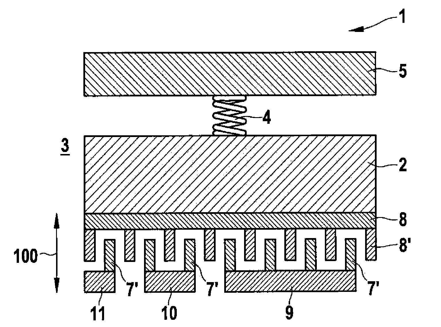
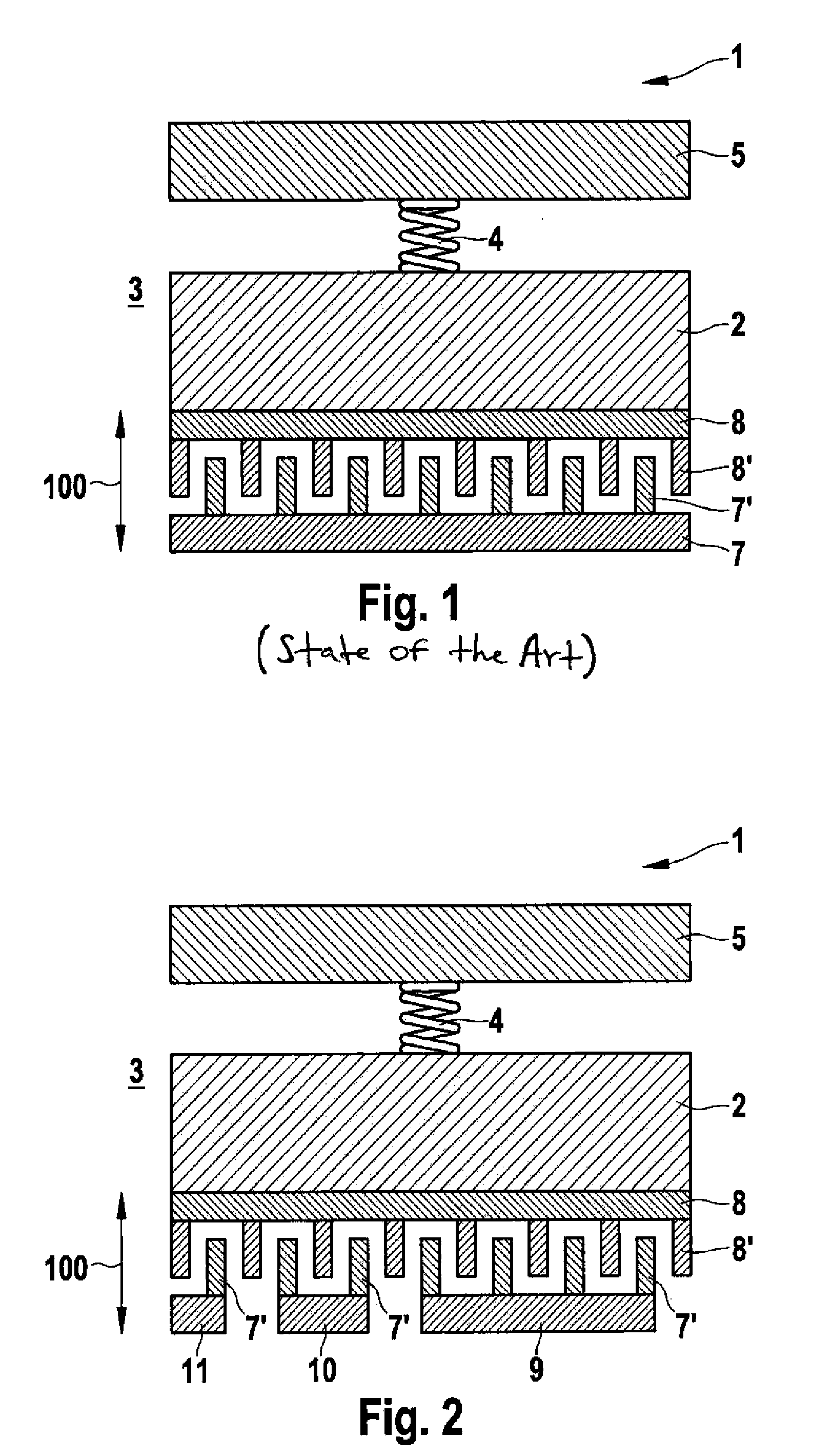
[0016]FIG. 1 shows a schematic plan view of a drive element 1 according to the related art, drive element 1 having a substrate 3 and a seismic mass 2. Seismic mass 2 is fastened to a retaining element 5 using a spring element 4 on substrate 3, so that seismic mass 2 is movable at least parallel to a main direction of motion 100 in relation to substrate 3. A stationary drive electrode 7 is situated on substrate 3, which is provided for the interaction with a counter-electrode 8 fastened to seismic mass 2. Counter-electrode 8 includes a plurality of counter-finger electrodes 8′ in this context and drive electrode 7 analogously includes a plurality of drive finger electrodes 7′. Counter-finger electrodes 8′ and drive finger electrodes 7′ are aligned essentially parallel to one another with respect to their main direction of extension, and parallel to main direction of motion 100, being situated parallel to substrate 3 and perpendicular to main direction of motion 100, offset to one ano...


PUM


Abstract

A drive element is provided having a substrate, a seismic mass, a drive electrode and a counter-electrode, one of the two electrodes being connected to the substrate and the other of the two electrodes being connected to the seismic mass; and the drive electrode and the counter-electrodes being provided for the excitation of motion of the seismic mass in a main direction of motion; and in addition, the drive electrode includes a first and a second partial electrode, which are switchable separately from each other.

Description

BACKGROUND INFORMATION[0001]Sensor systems are generally known. For example, a drive element is known from German Patent No. DE 198 08 549, a drive electrode and a counter-electrode being developed as intermeshing comb structures. A seismic mass is driven capacitively, using the drive electrode and the counter-electrode, the drive element, in particular, being wired up with square-wave voltages, which are applied to the drive electrode at an alternating frequency matched to the natural frequency of the sensor, and is converted there also to square-wave force pulses. However, the square-wave pulses which are applied to such a micromechanical pattern, include not only the desired natural frequency, but also higher frequency components. Even if the micromechanical pattern has a low-pass response because of its design, the higher frequency components contained in the drive signal may impinge on the additional mechanical modes of the complex pattern and likewise get these interfering mod...

Claims


Application Information

Patent Timeline
Patent Type & Authority Applications(United States)
IPC IPC(8): H02N1/00H03H9/24H03K4/02
CPCB81B3/0021B81B2203/0136B81B2203/04G02B5/284H02N1/008G02B26/0841G09G3/3433H03H9/02275G02B26/001
Inventor FRANKE, AXEL
Owner ROBERT BOSCH GMBH
Why Eureka
Try Eureka