Fluid-jet dissection system and method for reducing the appearance of cellulite
Active Publication Date: 2010-09-09
ULTHERA INC
View PDF156 Cites 52 Cited by
Summary
Abstract
Description
Claims
Application Information
AI Technical Summary
This helps you quickly interpret patents by identifying the three key elements:
Problems solved by technology
Method used
Benefits of technology
[0028]A further system for minimally invasive skin treatment is also disclosed. In this aspect, the system includes a recessed platform having a perimeter elevation and a top which cooperatively define a recessed area. An inner side of the perimeter elevation and the top define an apposition surface facing into the recessed area. Also included is a vacuum fitting operably connected to one of the top of the platform and the perimeter elevation of the platform and in fluid communication with the recessed area, and a vacuum pump in fluid communication with the vacuum fitting. The vacuum pump is preferably configured to supply a suction force to the recessed area to pull a tissue snugly and securely against the apposition surface when the recessed area is placed over the tissue. Multiple injection ports are provided on the platform and raised above the top of the platform, each injection port positioned about an entry hole through the top of the platform. Additionally, the system includes an injection device having a needle and a needle housing, the housing including an upper
Problems solved by technology
Furthermore, adipocyte expansion from weight gain may also stretch the septae.
This results in areas of the skin being held down while other sections bulge outward, resulting in the lumpy, ‘orange peel’ or ‘cottage cheese’ appearance on the skin surface.
Although a multitude of therapies exist, most of them do not provide a lasting effect on the skin irregularity, and some therapies may even cause the worsening of cellulite in certain patients.
Yet other treatments for cellulite have negative side effects that limit their adoption.
Regardless, most of these therapies require multiple treatments on an ongoing basis to maintain their effect at significant expense and with mixed results.
Such techniques may utilize a high intensity ultrasound wave that is focused on a tissue within the body, thereby causing a localized destruction or injury to cells.
Although low acoustic pressure ultrasound may somewhat heat tissue, the tissue is not heated sufficiently to cause direct tissue disruption or to enhance the ablation, and thus significantly reduces the risk of thermal damage to the dermis and associated structures (nerves, hair follicl
Method used
Image
Click on the blue label to locate the original text in one second.
Reading with bidirectional positioning of images and text.
Examples
Embodiment Construction
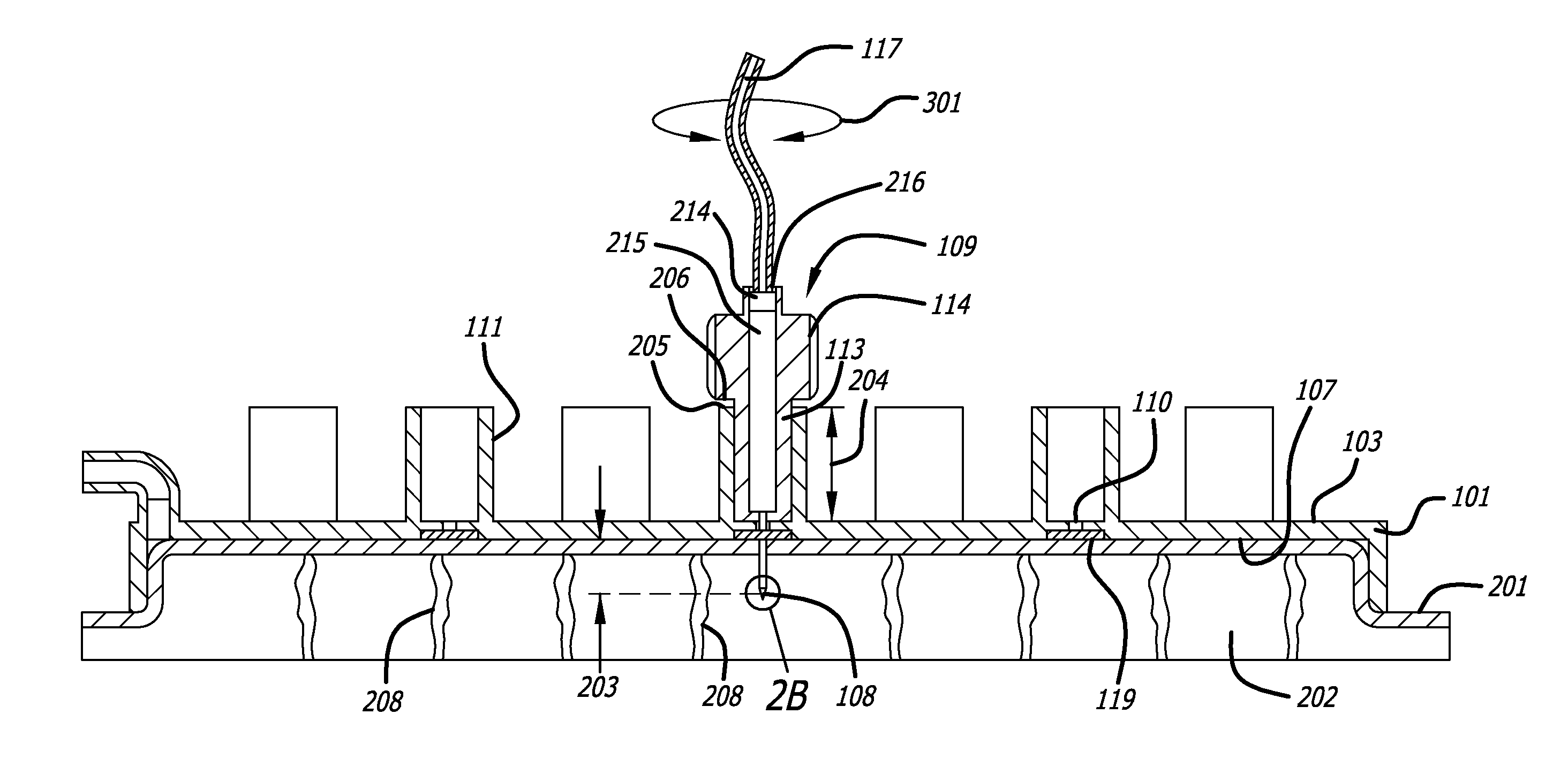
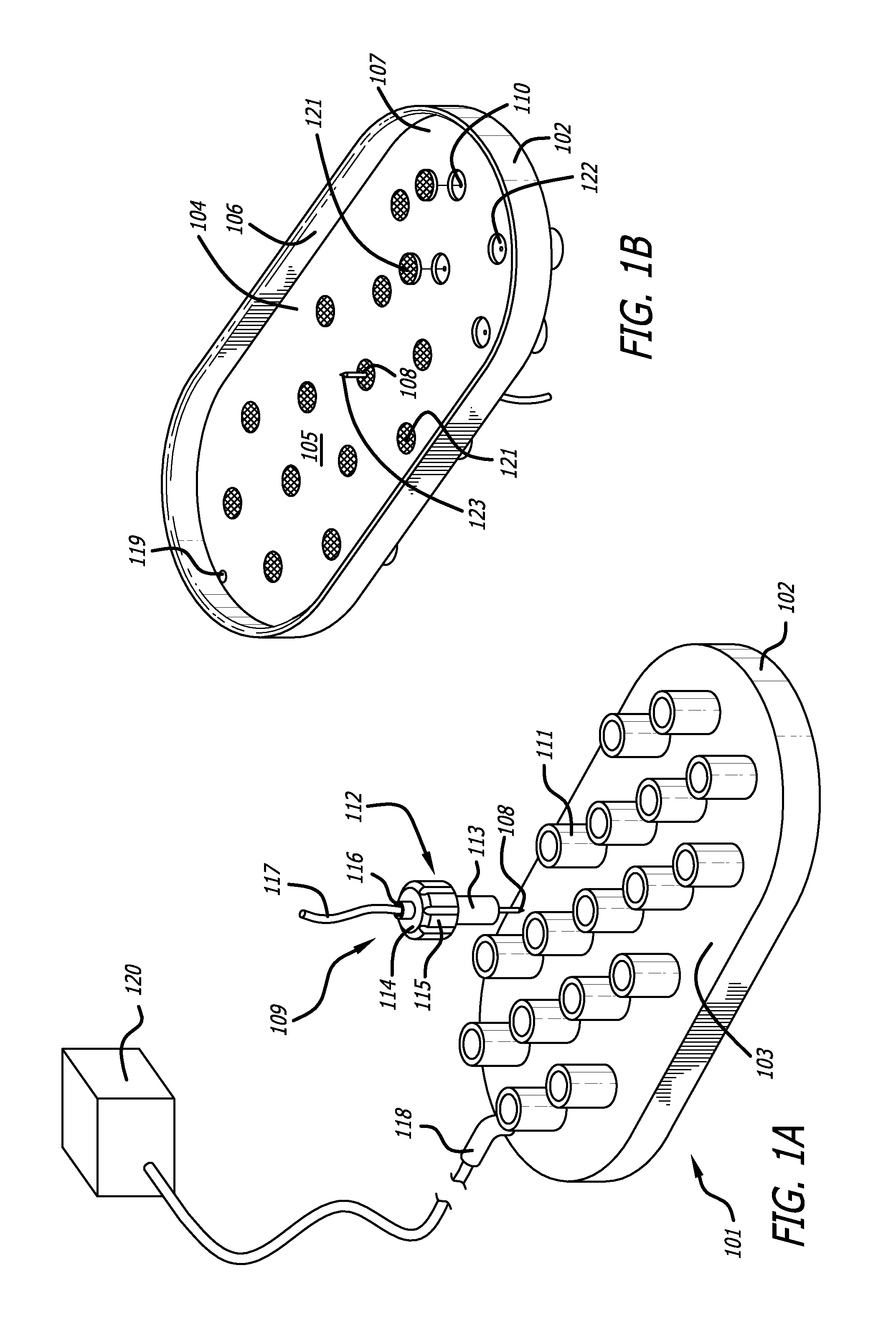
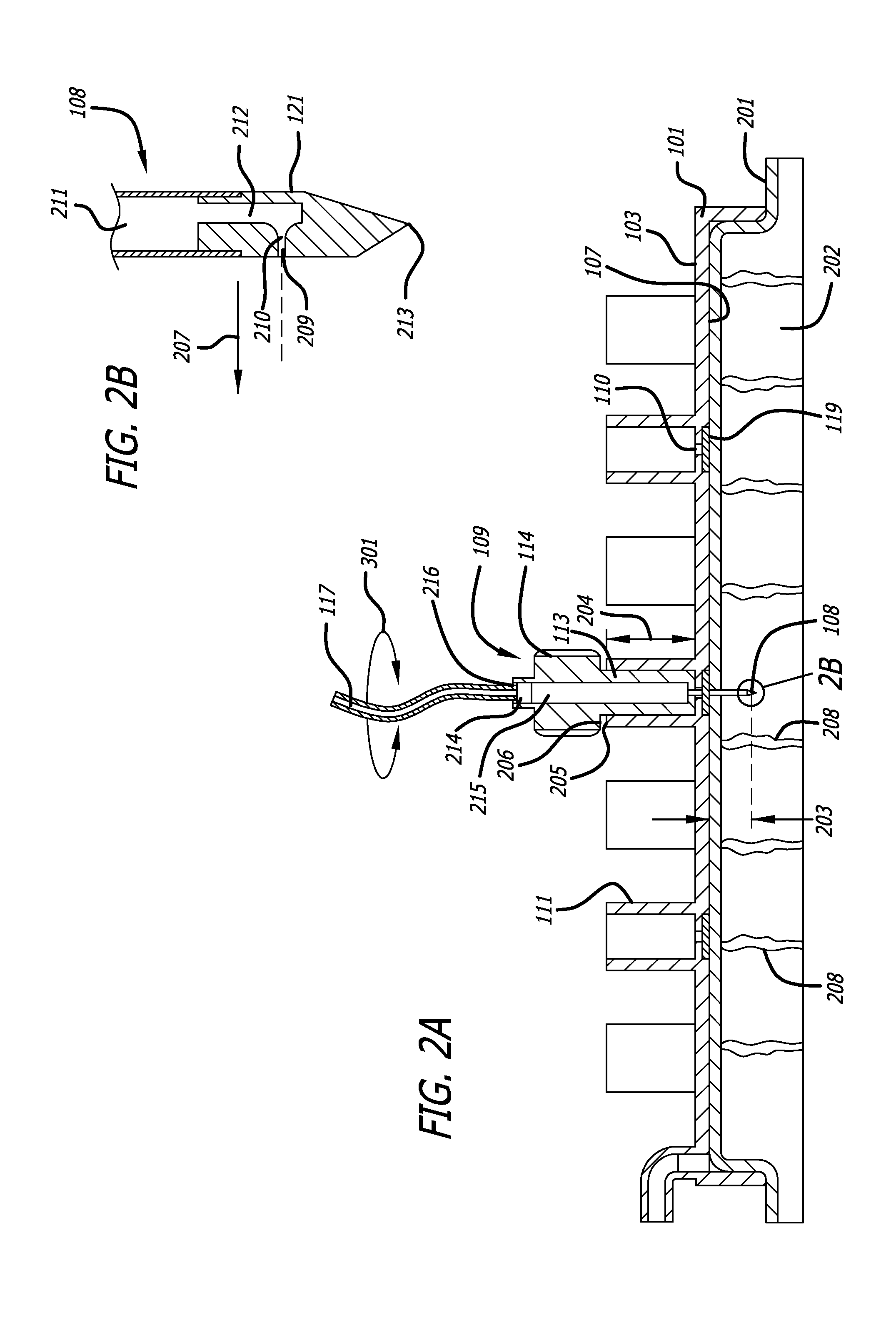
[0037]As depicted by FIGS. 1A and 1B, an embodiment of the system utilizes a platform 101 to capture and control a location of the skin, or dermis. Platform 101 preferably includes a downwardly extending wall or perimeter elevation 102 about the perimeter of platform 101 such that a bottom side of top 103 of platform 101 and perimeter elevation 102 collectively form recessed area 104 which can be placed over the dermis of a patient. An inner surface 105 of top 103 and inner side 106 perimeter elevation 102 further collectively form an apposition surface 107. By applying a force to the top of platform 101 or by a vacuum supplied to recessed area 104, a portion of a dermis can be moved in to recessed area 104 and against apposition surface 107 to substantially fill the recessed area, thus capturing it and providing some control over the area of tissue captured. This allows a needle 108 disposed on an injection device 109 to be inserted through an entry or through-hole 110 in top 103 o...
PUM
Abstract
A minimally invasive skin treatment system includes a platform having a recessed area on its bottom and one or more injection ports orthogonal to its top, each injection port including a through-hole to the recessed area. The system includes an injection device including a needle slidably disposed in a selective port such that the needle passes into the recessed area and percutaneously through a dermis disposed within the recessed area. A nozzle is configured to discharge a fluid at a high pressure in a direction orthogonal to an axis of the needle and parallel to the top of the platform to cut create a plane of dissection within the subcutaneous tissue.
Description
CROSS-REFERENCES TO RELATED APPLICATIONS[0001]This application is a continuation-in-part and claims priority from U.S. application Ser. No. 12 / 555,746, filed Sep. 8, 2009, which is a continuation-in-part and claims priority from U.S. application Ser. No. 11 / 515,634, filed Sep. 5, 2006, and U.S. application Ser. No. 11 / 334,794, filed Jan. 17, 2006 (now U.S. Pat. No. 7,588,547), both of which claim priority to U.S. Provisional Application No. 60 / 715,398, filed Sep. 7, 2005, and, all of which are incorporated by reference in their entirety. This application also is a continuation-in-part and claims priority from U.S. application Ser. No. 12 / 247,853, filed Oct. 8, 2008, which claims priority to U.S. Provisional Application No. 60 / 978,607, Oct. 9, 2007, both of which are incorporated by reference. Applicants claim priority to all of the applications in the chain.[0002]This application also claims priority from U.S. Provisional Application No. 61 / 232,385, filed Aug. 7, 2009, and U.S. Prov...
Claims
Application Information
Patent Timeline
Application Date:The date an application was filed.
Publication Date:The date a patent or application was officially published.
First Publication Date:The earliest publication date of a patent with the same application number.
Issue Date:Publication date of the patent grant document.
PCT Entry Date:The Entry date of PCT National Phase.
Estimated Expiry Date:The statutory expiry date of a patent right according to the Patent Law, and it is the longest term of protection that the patent right can achieve without the termination of the patent right due to other reasons(Term extension factor has been taken into account ).
Invalid Date:Actual expiry date is based on effective date or publication date of legal transaction data of invalid patent.