
Film forming apparatus, film forming method, computer program and storage medium

a technology of film forming and film forming method, which is applied in the direction of chemical vapor deposition coating, semiconductor/solid-state device details, coatings, etc., can solve the problems of increasing apparatus expenses (equipment expenses), insufficient filling of recesses, and insufficient sputtering methods to cope with ultrafine patterns that are expected in the future. , to achieve the effect of reducing apparatus expenses, excellent effects and high step coverag

Inactive Publication Date: 2010-09-16
TOKYO ELECTRON LTD +1
View PDF11 Cites 36 Cited by
  • Summary
  • Abstract
  • Description
  • Claims
  • Application Information

AI Technical Summary

Benefits of technology

[0014]The present invention has paid attention to the above-described problems and has been devised in order to effectively solve these problems. It is an object of the present invention to provide a film forming method, a film forming apparatus, a computer program and a storage medium, which allow even a fine recess to be filled with high step coverage by forming, for example, a CuMn alloy film or a Mn film, by heat treatment such as CVD, and which allow continuous processes to be performed in a same processing apparatus, thus greatly reducing apparatus expenses.

Problems solved by technology

However, although the CuMn Alloy can be formed only by the sputtering method at the current technical level, the sputtering method cannot sufficiently cope with ultrafine patterns that are expected in the future, e.g., trenches or holes having a line width or hole diameter of less than 32 nm.
Therefore, step coverage properties are deteriorated, so that the filling of the recesses can be insufficient.
Thus, there is a problem in that apparatus expenses (equipment expenses) are increased.
Furthermore, the process of forming the seeding film 6 and the filling process cannot be performed insitu.
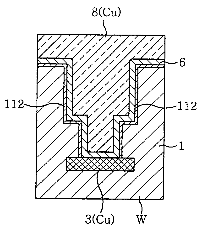
Thus, there are problems in that the highly reactive CuMn alloy film is oxidized and, as a result, the film formation of filled copper is deteriorated or Mn oxide formed by the oxidation of the Mn component of the seeding film increases contact resistance.
For this reason, there is a problem in that, even though a appropriately thin MnSixOy film is formed on the sidewall of the recess by an annealing process, manganese or its oxides, having resistance higher than that of copper, remain on the bottom in large amounts, leading to a significant increase in contact resistance.

Method used


Image

  • Film forming apparatus, film forming method, computer program and storage medium
  • Film forming apparatus, film forming method, computer program and storage medium
  • Film forming apparatus, film forming method, computer program and storage medium

Examples


Embodiment Construction

[0070]Hereinafter, the embodiments of a film forming method and film forming apparatus in accordance with the present invention will be described in detail with reference to the accompanying drawings.

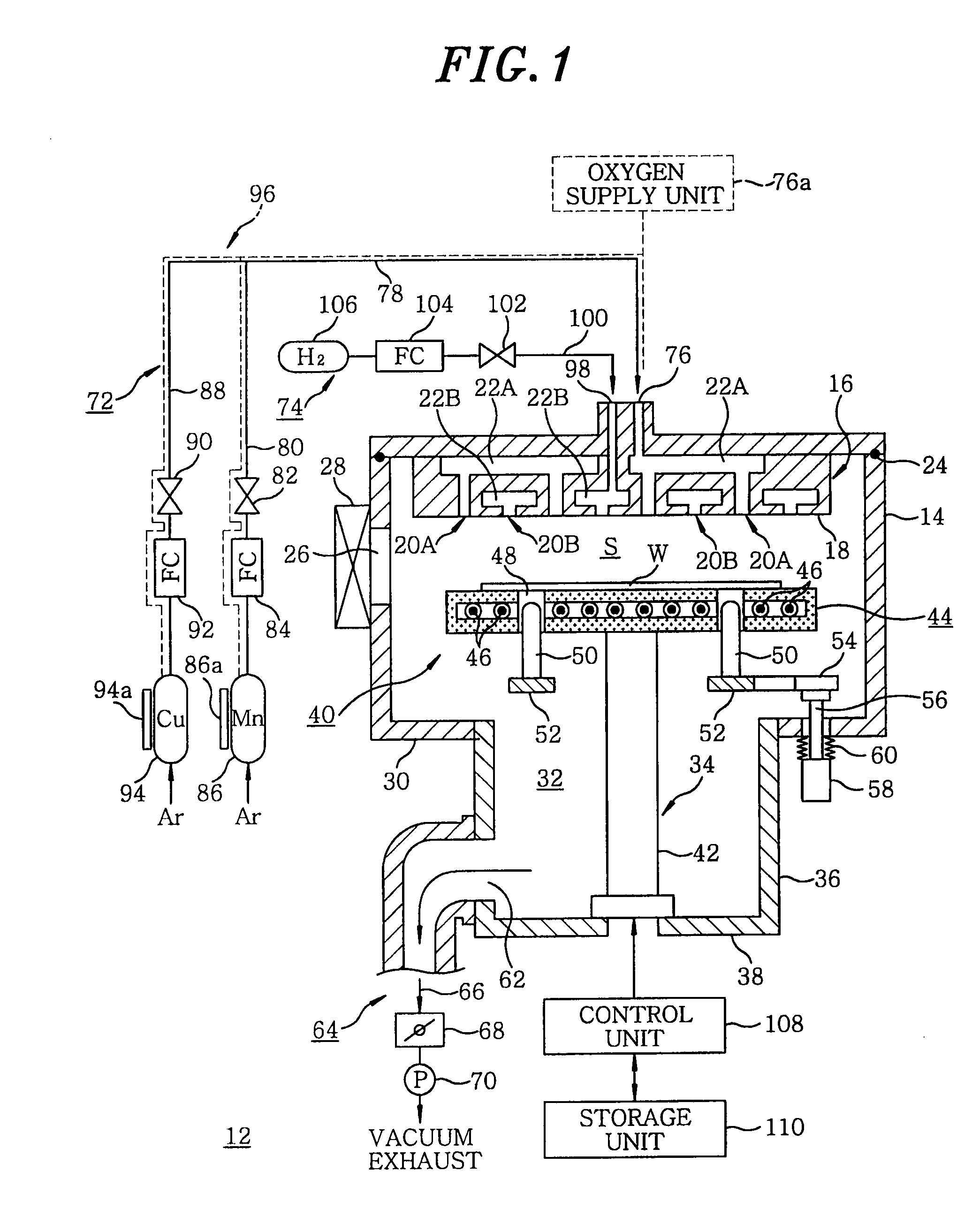
[0071]FIG. 1 is a configuration view showing one example of a film forming apparatus in accordance with the embodiments of the present invention. As shown therein, a film forming apparatus 12 in accordance with the embodiment of the present invention has a processing chamber 14 made of aluminum having a circular inner cross section. The sidewall of the processing chamber 14 is provided with a chamber heating unit (not shown) such as a heater rod for heating the chamber. The ceiling portion of the processing chamber 14 is provided with a shower head 16 that is a gas introducing unit for introducing a processing gas, e.g., a film forming gas. The shower head 16 has a gas injection surface 18 at the bottom surface thereof, and the processing gas is injected toward a processing space S from...


PUM

PropertyMeasurementUnit
Thicknessaaaaaaaaaa
Thicknessaaaaaaaaaa
Ratioaaaaaaaaaa

Abstract

In a film forming method, a substrate is first loaded into a vacuum-evacuable processing chamber. At least a transition metal-containing source gas and a reduction gas are supplied into the processing chamber, and the substrate is heated. Then, a thin film is formed in a recess in the surface of the substrate by heat treatment. Accordingly, the surface recess of the substrate can be filled with a copper film.

Description

FIELD OF THE INVENTION [0001]The present invention relates to a film forming apparatus and a film forming method for forming, e.g., a copper-manganese (CuMn) alloy film or a manganese (Mn) film, as a seeding film, on a surface of a substrate to be processed such as a semiconductor wafer and the like.BACKGROUND OF THE INVENTION[0002]In general, a desired semiconductor device is manufactured by repeatedly performing various processes such as a film forming process or a pattern etching process on a semiconductor wafer. With a demand for high integration and miniaturization of semiconductor devices, line widths or hole diameters are getting smaller. In addition, as a wiring material or a filling material for filling recesses such as trenches or holes, copper which has low electrical resistance and is inexpensive is being widely used in order to satisfy the need to reduce electrical resistance due to the miniaturization of various dimensions (Patent Document 1). When copper is used as th...

Claims


Application Information

Patent Timeline
IPC IPC(8): H01L21/768C23C16/458
CPCC23C16/18C23C16/45529H01L2924/0002C23C16/45565C23C16/45574H01L21/28556H01L21/28562H01L21/76831H01L21/76844H01L21/76864H01L21/76871H01L21/76877H01L23/53238H01L2221/1089H01L2924/09701H01L2924/00H01L23/52H01L21/285H01L21/3205
Inventor MATSUMOTO, KENJIKOIKE, JUNICHINEISHI, KOJI
Owner TOKYO ELECTRON LTD
Learn More