
Hybrid welding repair of gas turbine superalloy components

a technology of superalloy components and hybrid welding, which is applied in the direction of machines/engines, climate sustainability, crystal growth process, etc., can solve the problems of further damage, corrosion, oxidation, and deterioration of structural integrity of the structure,

Inactive Publication Date: 2010-09-23
HONEYWELL INT INC
View PDF20 Cites 27 Cited by
  • Summary
  • Abstract
  • Description
  • Claims
  • Application Information

AI Technical Summary

Benefits of technology

The present invention provides methods for repairing a degraded section of a turbine blade. The methods involve depositing a layer of a material that is resistant to corrosion and oxidation on the degraded section using electro-spark deposition, followed by laser welding a layer of a second material onto the first layer to form a repaired section. The repaired section is then machined to an original configuration. The invention allows for the efficient repair of degraded sections of turbine blades, reducing downtime and improving operational efficiency.

Problems solved by technology

Consequently, the blades are subjected to high heat and stress loadings which, over time, may degrade their structural integrity.
Although nickel-based and cobalt-based superalloys have good high temperature properties and many other advantages, they may be susceptible to corrosion, oxidation, thermal fatigue and erosion damage in the high temperature environment of turbine engine operation.
However, blades having internal cooling channels are already relatively thin-walled; thus, laser welding in the thin-wall airfoils may cause further damage thereto.
Additionally, because laser welding melts a shallow surface of the blade to form metallurgical bonding, the repaired blade walls that make up the internal cooling channel may become misshapen.
Consequently, the airflow through the flowpath may be greatly affected.
Although electro-spark deposition is a low heat process that allows material to be deposited with negligible damage to the original blade and with little danger of affecting the cooling channels, deposits made with the process tend to contain high levels of defects such as porosity that can affect mechanical properties.
It is also a very slow process, impacting practicality for widespread use.

Method used


Image

  • Hybrid welding repair of gas turbine superalloy components
  • Hybrid welding repair of gas turbine superalloy components
  • Hybrid welding repair of gas turbine superalloy components

Examples


Embodiment Construction

[0015]The following detailed description of the invention is merely exemplary in nature and is not intended to limit the invention or the application and uses of the invention. Furthermore, there is no intention to be bound by any theory presented in the preceding background of the invention or the following detailed description of the invention.

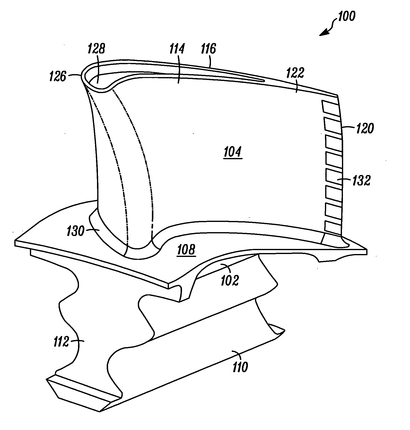
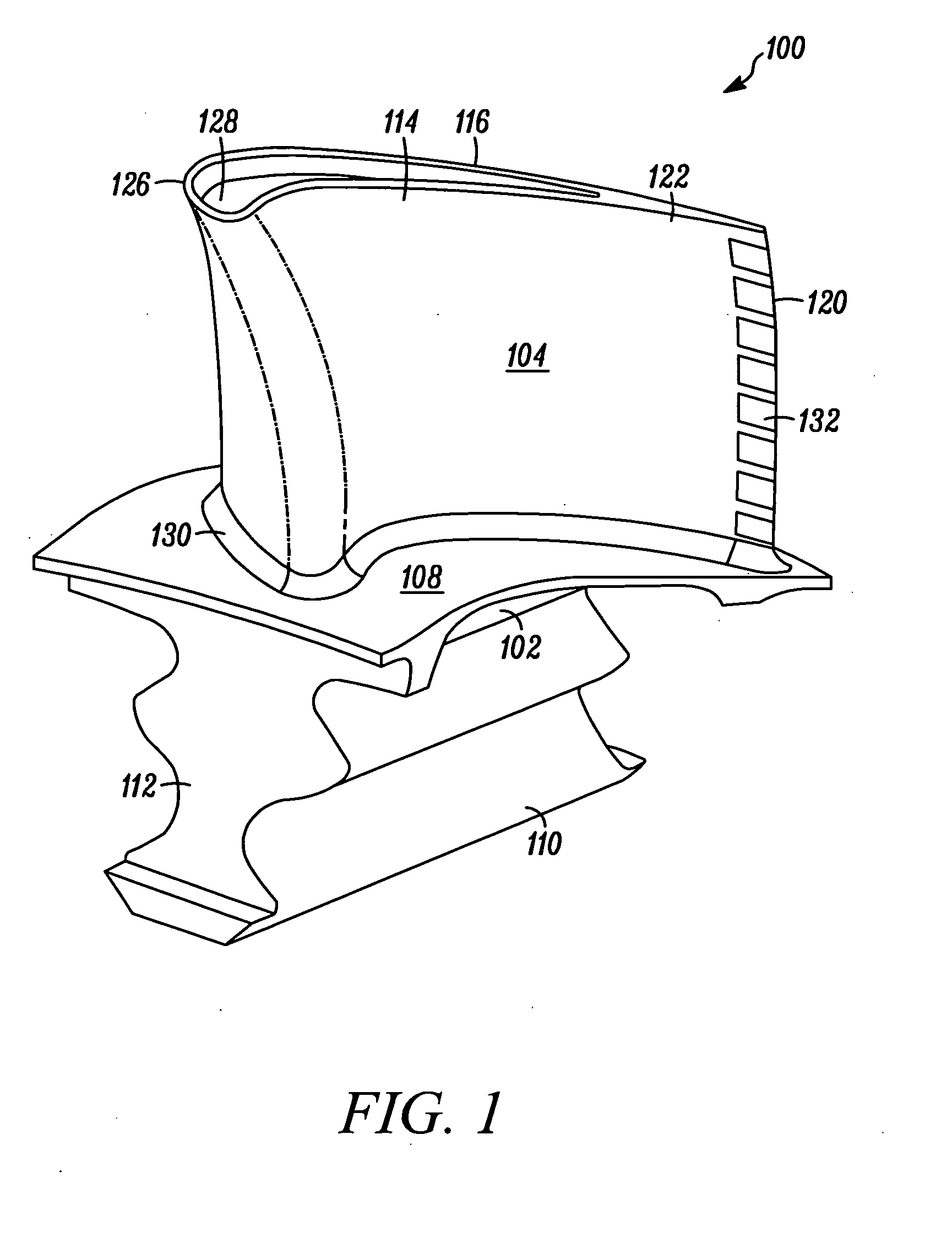
[0016]FIG. 1 illustrates an exemplary aircraft jet engine turbine rotor blade 100. The blade 100 is preferably made of a base material and may include various coatings thereon for protection thereof. In one exemplary embodiment, the base material is a nickel-based superalloy, and may be, for example, such as SC180, MarM247, C101, IN713, or IN738. It will be appreciated that other suitable materials may alternatively be used. The protective coatings may be one of numerous suitable materials that are corrosive and oxidation resistant, such as environment-resistant diffusion aluminide and / or MCrAlY overlay coatings.

[0017]The blade 100 depicted ...


PUM

PropertyMeasurementUnit
corrosion resistantaaaaaaaaaa
oxidation resistantaaaaaaaaaa
currentaaaaaaaaaa

Abstract

Methods are provided for repairing a degraded section of a turbine blade, the turbine blade comprising a base material. In one embodiment, and by way of example only, the method includes the step of electro-spark depositing a first material on the turbine blade degraded section to form an intermediate layer thereon, the first material comprising a material that is substantially similar to the base material. Next, a second material is laser welded onto the intermediate layer to form a repaired section. This invention combines the low-heat input of electro-spark deposition with the high welding quality and high deposition rate of laser powder fusion welding.

Description

TECHNICAL FIELD[0001]The present invention relates to gas turbine engines and, more particularly, to methods for repairing superalloy components of the gas turbine engines.BACKGROUND[0002]Gas turbine engines, such as turbofan gas turbine engines, may be used to power various types of vehicles and systems, such as, for example, aircrafts. Typically, these engines include turbine blades (or airfoils) that are impinged by high-energy compressed air that causes a turbine of the engine to rotate at a high speed. Consequently, the blades are subjected to high heat and stress loadings which, over time, may degrade their structural integrity.[0003]To improve structural integrity and durability of gas turbine engines, the turbine blades have been fabricated from high-temperature materials such as nickel-based and cobalt-based superalloys, and can include internal cooling systems formed therein that maintain the temperatures thereof within superalloy tolerating limits. Typically, the blades a...

Claims


Application Information

Patent Timeline
Patent Type & Authority Applications(United States)
IPC IPC(8): B23P6/00
CPCB23K9/044B23K26/34B23K2201/001B23P6/007F01D5/005F05D2230/234Y10T29/49318F05D2230/31B23K26/3213B23K26/345B23K35/3033C30B29/52F05D2230/12B23K26/32B23K26/342B23K2101/001B23K2103/18B23K2103/26Y02T50/60
Inventor HU, YIPINGBYE, RICHARD L.TAYLOR, CLYDE R.
Owner HONEYWELL INT INC
Learn More