Non-destructive testing systems and methods

Active Publication Date: 2010-09-23
PROTO MANUFACTURING LTD
View PDF5 Cites 28 Cited by
  • Summary
  • Abstract
  • Description
  • Claims
  • Application Information

AI Technical Summary

Benefits of technology

[0030]In another aspect, a method for determining an unknown orientation angle of a crystalline material in an article having an overlying polycrystalline layer is provided. As described above, the method allows for non-destructively testing the article such that the article may be placed into s

Problems solved by technology

While, for example, the orientation angle of the underlying material may not be able to be directly tested due to the presence of the overlying polycrystalline layer, it has been discovered that the overlying layer is directly responsive to variations in the underlying material under different loading conditions.
More specifically, while it may not be possible to directly measure the crystal orientation of the underlying SX or

Method used


Image

  • Non-destructive testing systems and methods
  • Non-destructive testing systems and methods
  • Non-destructive testing systems and methods

Examples


Embodiment Construction

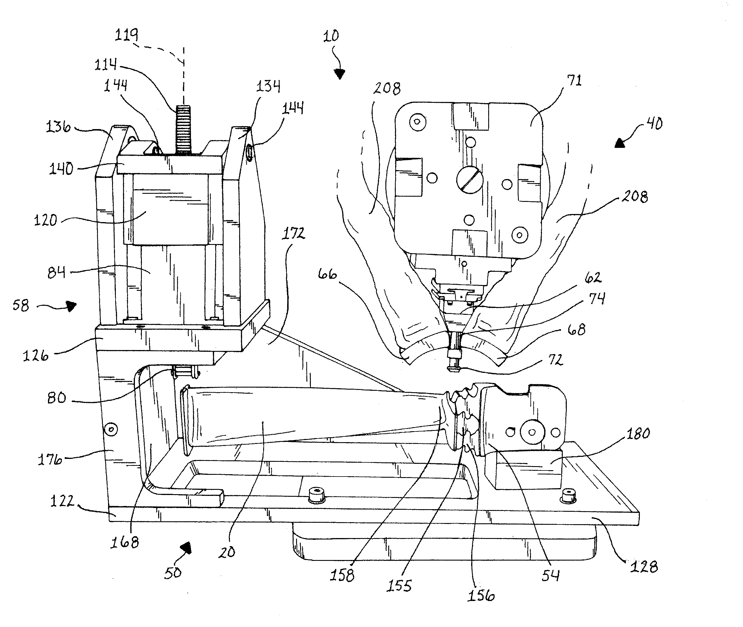
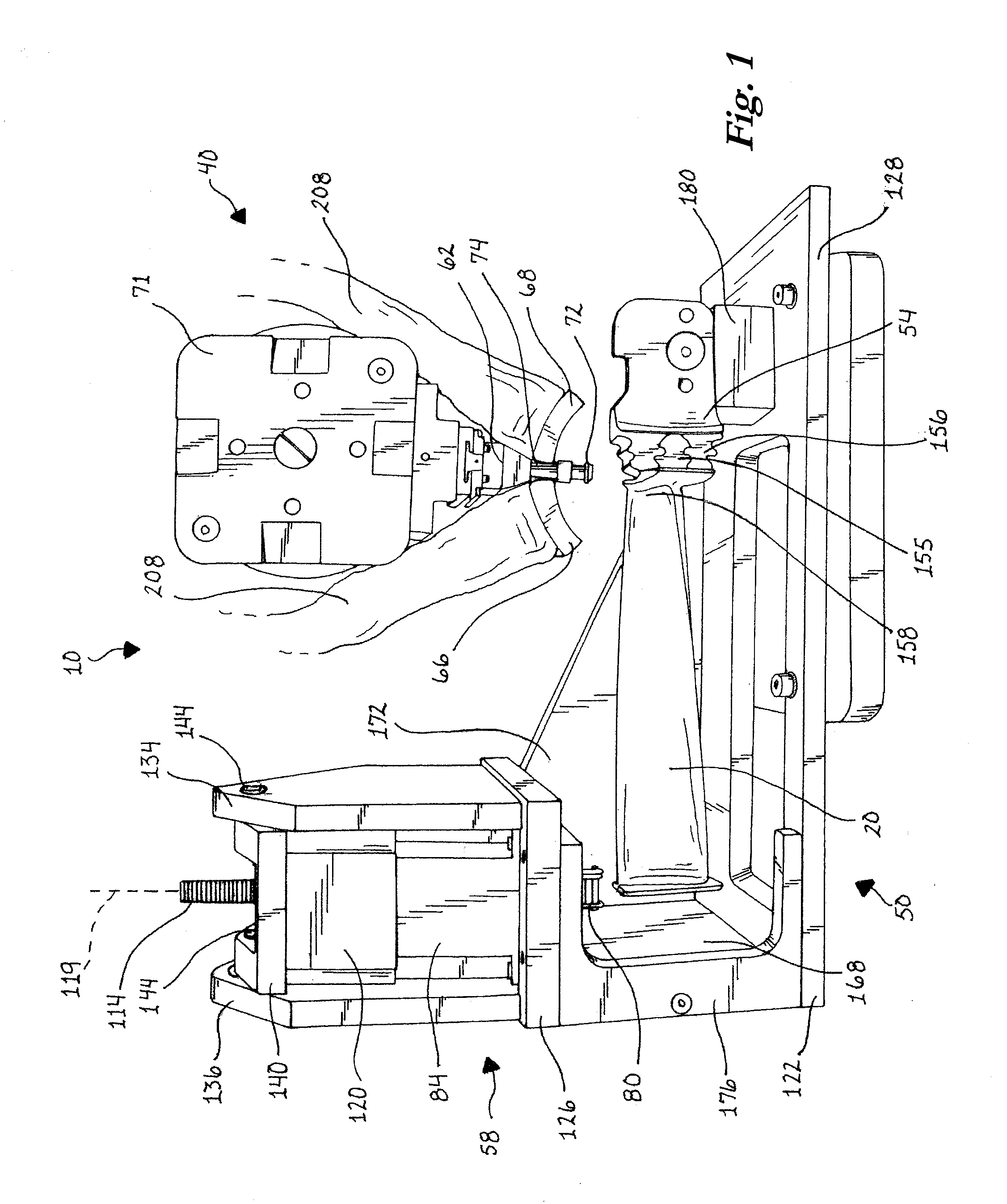
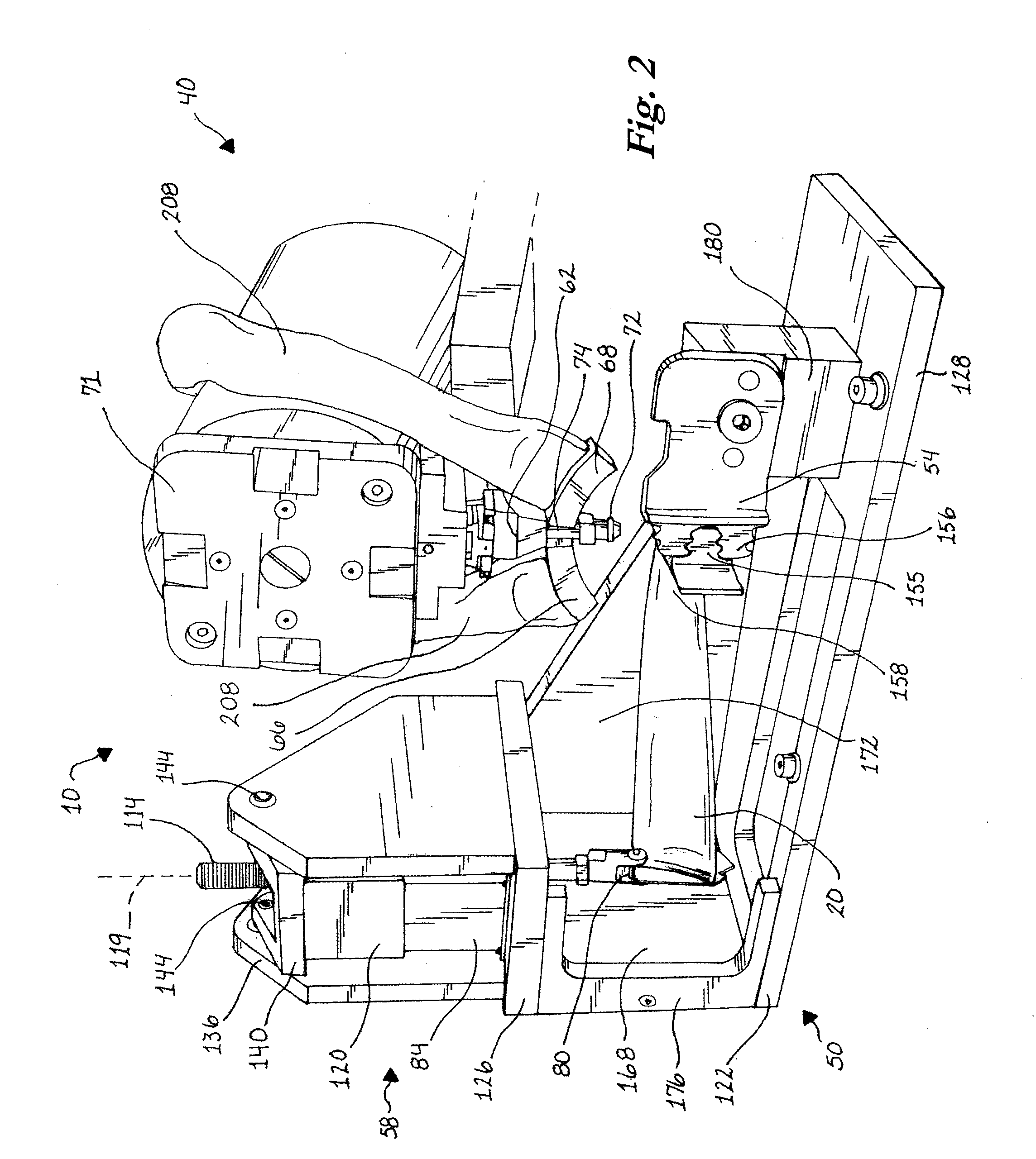
[0044]Referring FIGS. 1-4, an x-ray diffraction system 5 including an x-ray diffraction apparatus 10 for analyzing a representative article 20 in accordance with the present invention is illustrated. The article 20, as depicted in FIG. 8A, may, for example, be a rotor blade for use in a turbine. The blade 20, as shown in cross-section in FIG. 8B, is depicted as having two materials. The main body 22 of the blade 20 is a crystalline material, such as a SX material or DS material as previously described. These materials are widely used when low weight and certain material characteristics, such as high strength characteristics, are important. The crystalline material 22 has a further material characteristic, namely grain orientation, which when properly aligned with the highest stress direction of the article 20 provides an article with a greater amount of stress resistance than if the grain orientation was out of alignment with the proper alignment. Further, as strength, elastic, and ...


PUM


Abstract

A system and method for non-destructively determining the grain orientation of a crystalline material using x-ray diffraction techniques to non-destructively analyze material and, more particularly, to a system and method for determining the grain orientation of an underlying crystalline material covered by an overlying polycrystalline material. Further, the system and method relate to the use of x-ray diffraction to non-destructively characterize parts and components to determine whether to accept or reject those components or parts for use in application.

Description

CROSS-REFERENCE TO RELATED APPLICATION[0001]This application claims benefit of U.S. Provisional Application No. 61 / 162,098, filed Mar. 20, 2009, which is hereby incorporated herein by reference in its entirety.FIELD OF THE INVENTION[0002]The invention relates to a system and method for non-destructively determining the grain orientation of a crystalline material using x-ray diffraction techniques to non-destructively analyze material and, more particularly, to a system and method for determining the grain orientation of an underlying crystalline material covered by an overlying polycrystalline material. Further, the field relates to the use of x-ray diffraction to non-destructively characterize parts and components to determine whether to accept or reject those components or parts for use in application.BACKGROUND OF THE INVENTION[0003]Fatigue-limited metal components of gas turbines or jet engines, or other machine components subject to metal fatigue or failure, are carefully manag...

Claims


Application Information

Patent Timeline
IPC IPC(8): G01N23/20G01N29/04G01N27/82G01N23/00
CPCG01N3/32G01N23/20G01N2291/0289G01N29/30G01N2203/0075G01N29/043
Inventor BELASSEL, MOHAMMEDBRAUSS, E. MICHAELPINEAULT, JAMES A.DRAKE, ROBERT JOHN
Owner PROTO MANUFACTURING LTD
Why Eureka
Try Eureka