

Image-Guided Minimal-Step Placement Of Screw Into Bone
- Summary
- Abstract
- Description
- Claims
- Application Information
AI Technical Summary
Benefits of technology
Problems solved by technology
Method used
Image

Examples
first embodiment
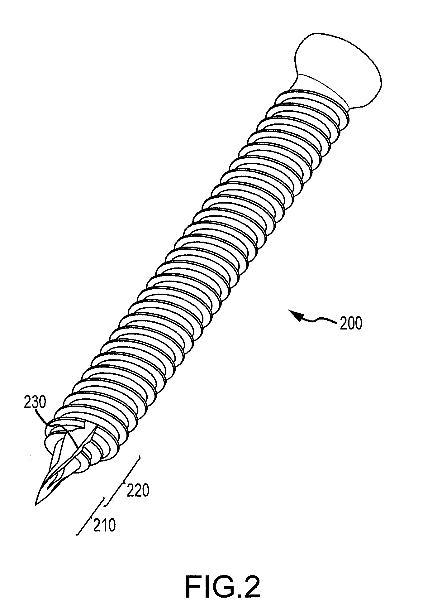
[0049]FIG. 2 is an illustration of a specialized screw as described herein.
[0050]Specialized screw 200 illustrates a first embodiment of a specialized self-drilling, self-tapping screw. A specialized screw may refer to any suitable screw that may be used in combination with a powered driving device, as described herein, for insertion into bone. Further, suitable screws may or may not comprise each feature of the described embodiment, e.g., specialized screw 200, including described self-drilling and / or self-tapping features. That is, other suitable screw designs may be inserted into bone via a powered driving device as disclosed herein and may be included within the scope of the present disclosure.
[0051]According to embodiments, specialized screw 200 may be made of any suitable, non-toxic, material for insertion into a bone. Suitable materials may include, but are not limited to, titanium and stainless steel. Specialized screw 200 may further include a plurality of screw portions. F...
second embodiment
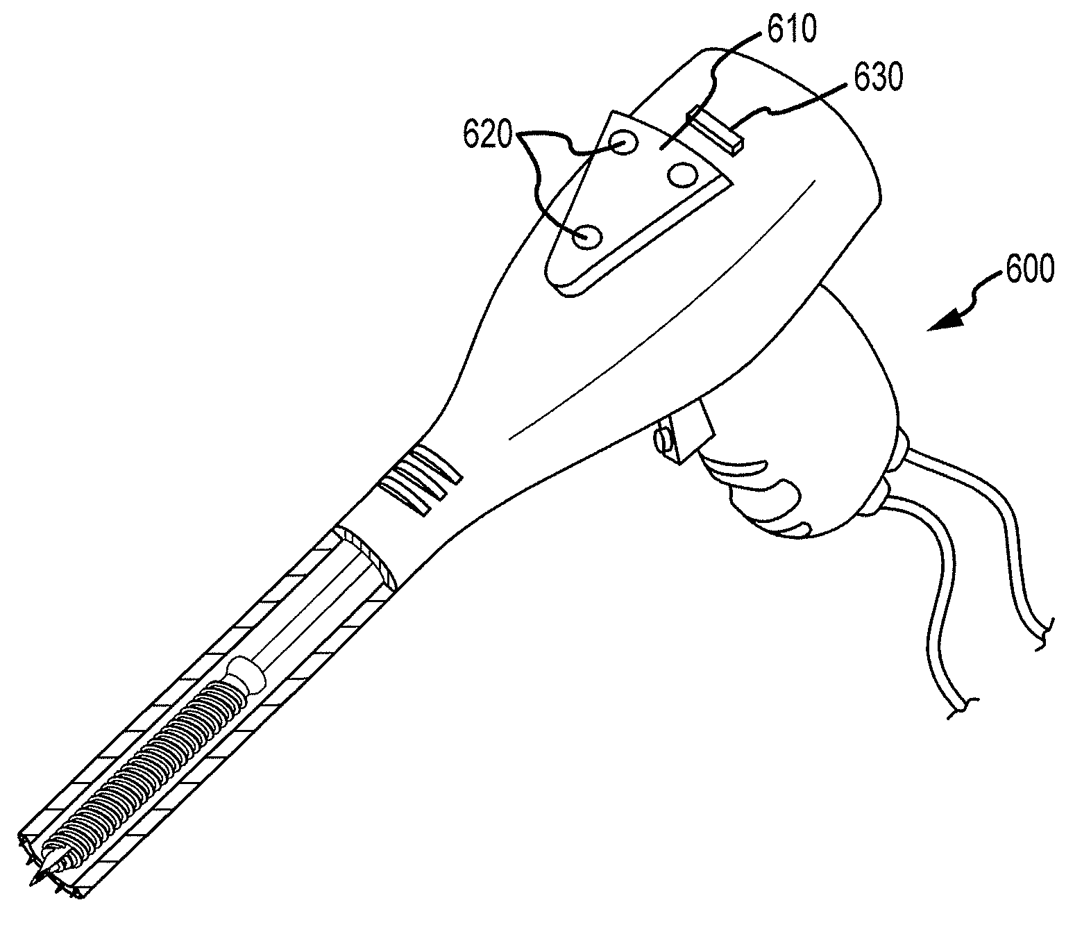
[0094]FIG. 5 is an illustration of a powered driving device as described herein.
[0095]According to embodiments, the second embodiment of a powered driving device, e.g., powered driving device 500, may be substantially similar to powered driving device 400. According to some embodiments, FIG. 5 provides additional illustrative description for features not visible in FIG. 4.
[0096]According to embodiments, powered driving device 500 may comprise any suitable powered driving device for accurately inserting a specialized screw into a bone. As described above, powered driving device 500 may further comprise an elongated, cylindrical drive chamber 510. According to embodiments, drive chamber 510 may be adjustable or otherwise altered for accommodating various types and sizes of specialized screws, as with drive chamber 410. According to alternative embodiments, a plurality of different sized drive chambers 510 may be manufactured corresponding to particular specialized screw types and size...
third embodiment
[0170]FIG. 11 is a flow-diagram illustrating a method for automatically shutting down a powered driving device during screw placement.
[0171]At initiate operation 1102, after verification of a projected placement of the specialized screw using the image-guidance system or otherwise, the powered driving device may be initiated, as described above.
[0172]At monitor operation 1104, a position of the specialized screw may be monitored by sensors during insertion of the specialized screw. For example, according to embodiments, suitable sensors may be employed to detect a bone density around the specialized screw. As a bone density of the cortical layer may be greater than a bone density of the trabecular layer, bone density may be used to indicate that a specialized screw is approaching the cortical layer and is in danger of traversing and / or fracturing the bone. Alternatively, other suitable sensors may be employed to detect a proximity of the specialized screw to the cortical layer via a...
PUM
 Abstract
Description
Claims
Application Information