

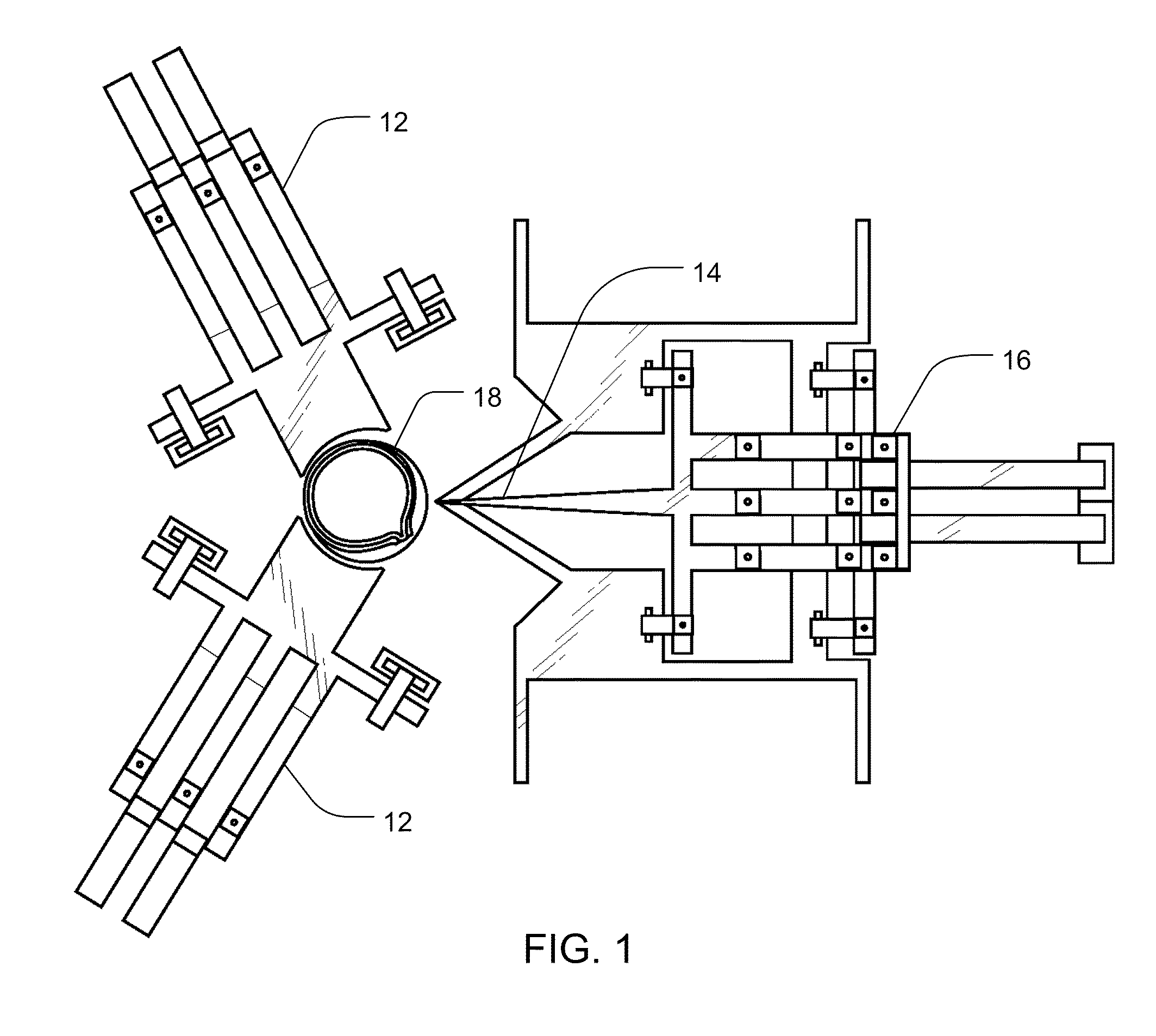
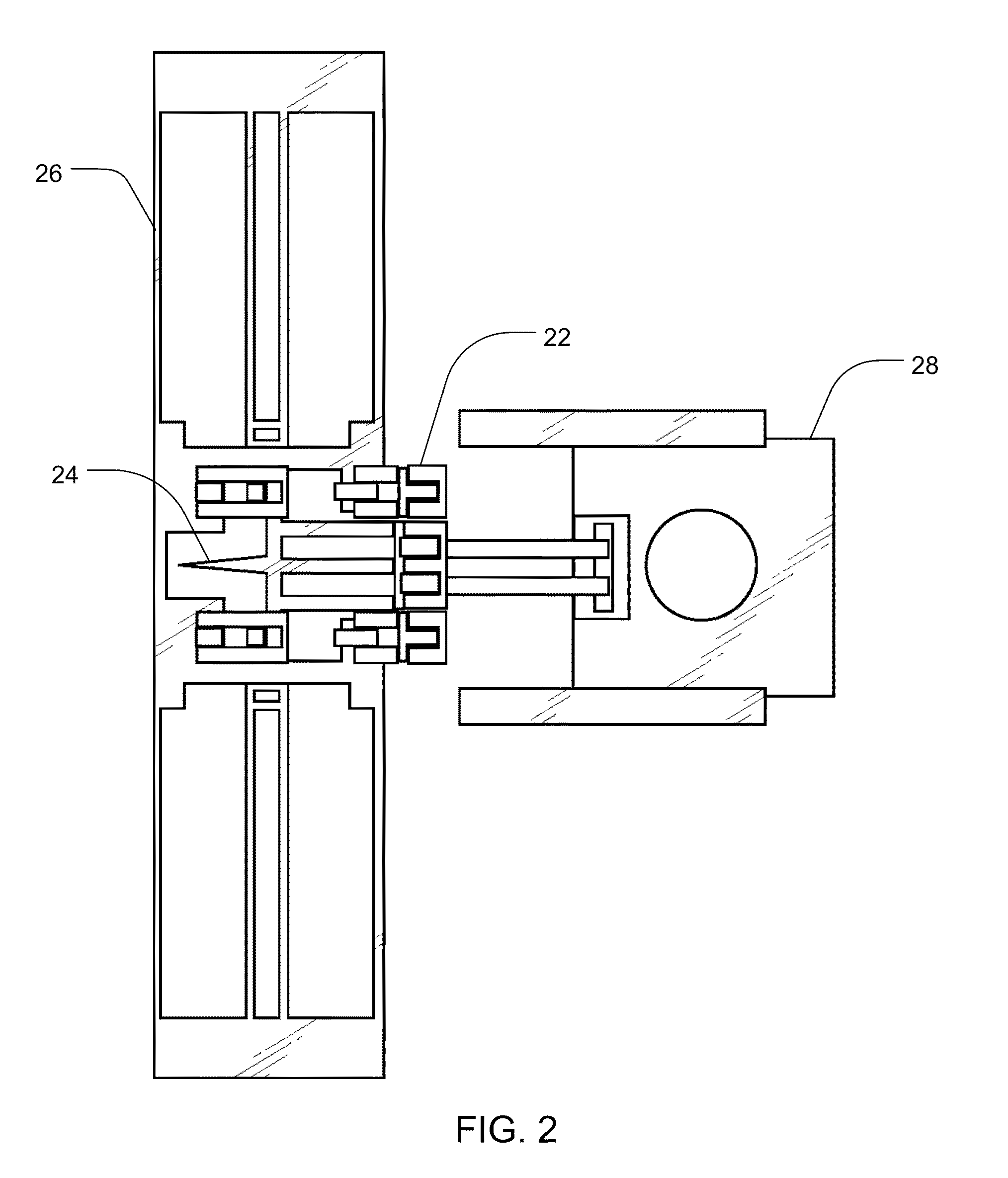
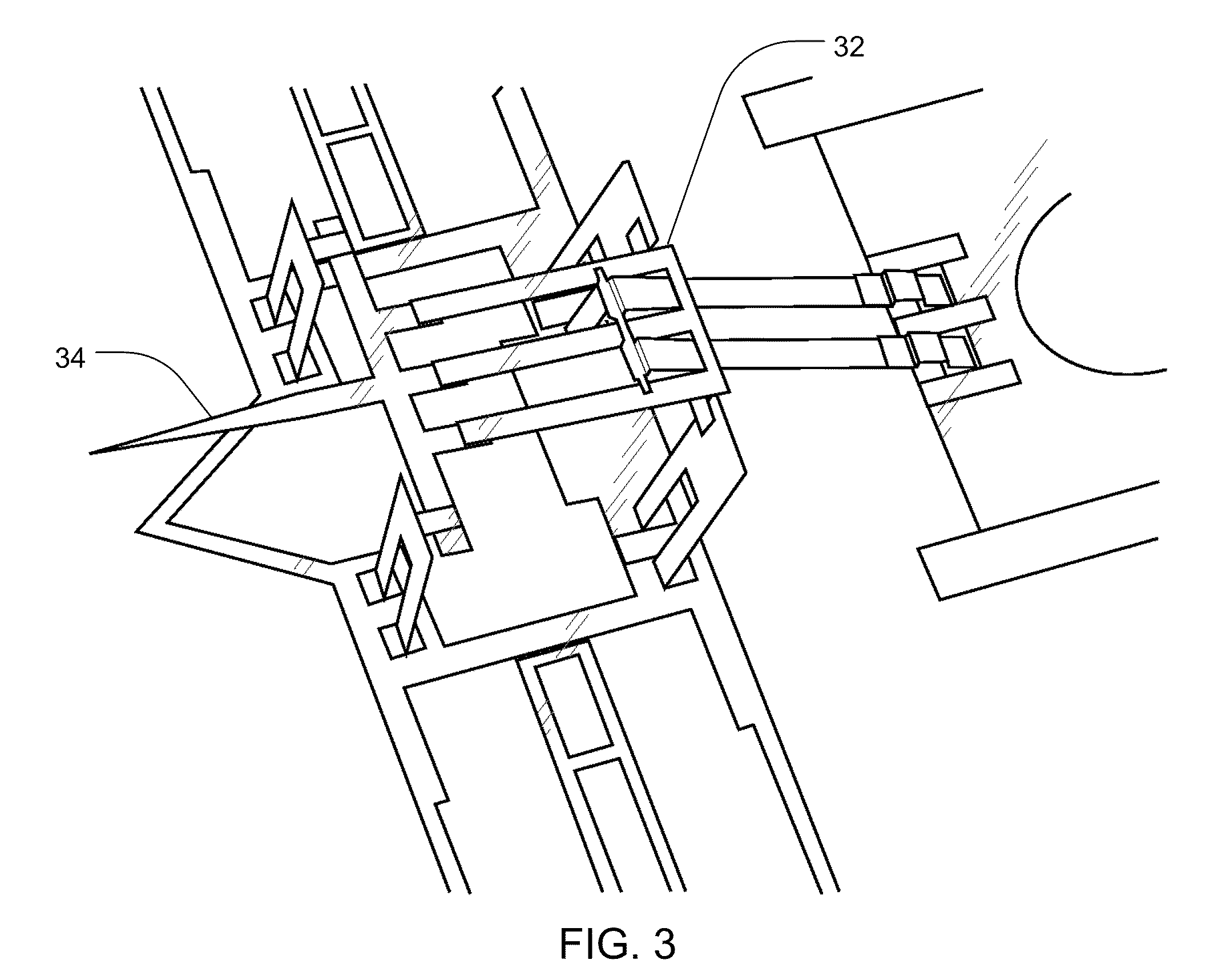
Methods and Devices for Charged Molecule Manipulation
a charge molecule and charge technology, applied in the field of micromanipulation of charged molecules, can solve the problem of often problematic microinjection of foreign materials
- Summary
- Abstract
- Description
- Claims
- Application Information
AI Technical Summary
Benefits of technology
Problems solved by technology
Method used
Image

Examples
example 1
DNA Visualization and Imaging Methods
[0055]4′,6-diamidino-2-phenylindole dihydrochloride (DAPI) is used to visualize the DNA in the following example. DAPI exhibits low toxicity and its strong fluorescence under ultra-violet illumination. When dissolved in water and not bound to DNA, DAPI has an excitation maximum of 355 nm (ultra-violet light) and an emission maximum of 453 nm (blue light). When DAPI is bound to DNA its excitation maximum changes to 388 nm and its emission maximum shifts to 454 nm, and the intensity of the emitted light increases roughly twenty-fold compared to free DAPI. The increase in emission intensity when DAPI binds with DNA makes it possible to distinguish between unbound DAPI and DAPI-stained DNA.
[0056]DAPI-stained DNA is visualized using a Zeiss Axioskop Fluorescence Microscope with UV illumination and a purpose-built blue light filter for imaging DAPI stained samples. Because the DAPI-DNA complex fluoresces in the blue portion of the visible spectrum, the...
example 2
DNA Attraction Experiment
[0057]The DNA attraction and repulsion experiments are performed both in distilled water and in 0.9% saline solution. In both cases, the experiments follow identical protocols, with the exception of the media into which the device is submerged. A MEMS device as has been described herein is covered in approximately 2 mm of either distilled water or 0.9% saline solution. A 1-2 μL drop of 306 ng / μL DAPI stained DNA is placed in the solution near the device using a calibrated pipette. The needle structure of the MEMS device is connected to the positive terminal of a voltage source providing 1.5 V DC. The substrate of the MEMS device is connected to the negative terminal of the voltage source. Images can be taken to verify the DAPI-stained DNA on the surface of the needle structure. Approximate concentrations of the DNA can be calculated using the linear model of Equation I.
example 3
DNA Repulsion Experiment
[0058]DNA is attracted to the tip of a MEMS needle structure as is described in Example 2, by connecting the needle structure to the positive terminal of a 1.5 V DC voltage source and connecting the MEMS device substrate to the negative terminal of the voltage source. Following attraction of DNA, the polarity of the electrical charge is then reversed so that the positive terminal is connected to the MEMS device substrate and the negative terminal is connected to the needle structure. Images can be taken from the time the polarity is reversed to verify DNA release and repulsion. Additionally, the time between connecting the MEMS needle structure to the negative terminal and when DNA is clearly repelled from the needle structure can be calculated, and approximate concentrations can be calculated using the linear model given in Equation I.
PUM
| Property | Measurement | Unit |
|---|---|---|
| diameter | aaaaa | aaaaa |
| diameter | aaaaa | aaaaa |
| diameter | aaaaa | aaaaa |
Abstract
Description
Claims
Application Information