Porous implant with effective extensibility and methods of forming an implant

Inactive Publication Date: 2010-09-30
EVERA MEDICAL
View PDF3 Cites 558 Cited by
  • Summary
  • Abstract
  • Description
  • Claims
  • Application Information

AI Technical Summary

Benefits of technology

[0012]Also disclosed herein is a method of forming an implant. The method can include the steps of: providing a first layer of ePTFE, a second layer of ePTFE and an inner element, the first and second layers having a width and a length, the first and second layers of ePTFE comprising a plurality of nodes and a plurality of fibrils extending between the nodes; reducing the length of the ePTFE layer at least 5% while maintaining a smooth surface. The reducing step can be carried out so that a distance between the nodes is decreased along the length while maintaining the nodes in a substantially flat layer. The fibrils between the nodes can be deformed to accommodate the reduction in length. The first layer of ePTFE can be stretched to increase the width of the first ePTFE layer. The first and second layers of ePTFE can be attached to the inner element after the reducing and stretching steps. The first layer can be exposed to native tissue, while the second layer is positioned between the first layer and the inner element.
[0013]Another aspect of the invention is an implant which may be implanted into a patient that includes a fi

Problems solved by technology

A problem which is encountered when using some porous materials such as ePTFE to cover an implant is that ePTFE can be relatively rigid and inelastic in one or more directions due to the inhere

Method used


Image

  • Porous implant with effective extensibility and methods of forming an implant
  • Porous implant with effective extensibility and methods of forming an implant
  • Porous implant with effective extensibility and methods of forming an implant

Examples


Embodiment Construction

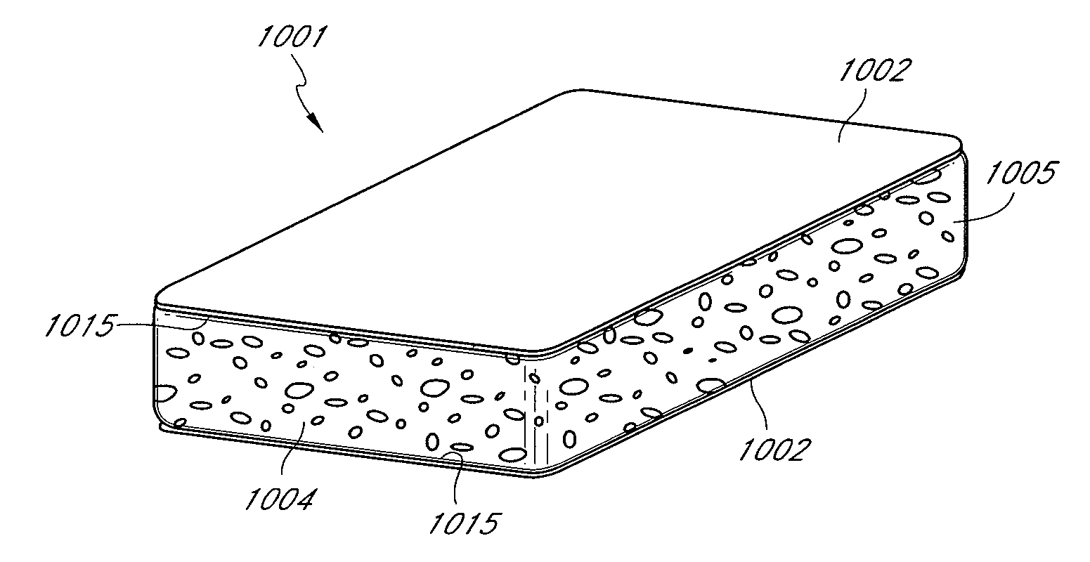
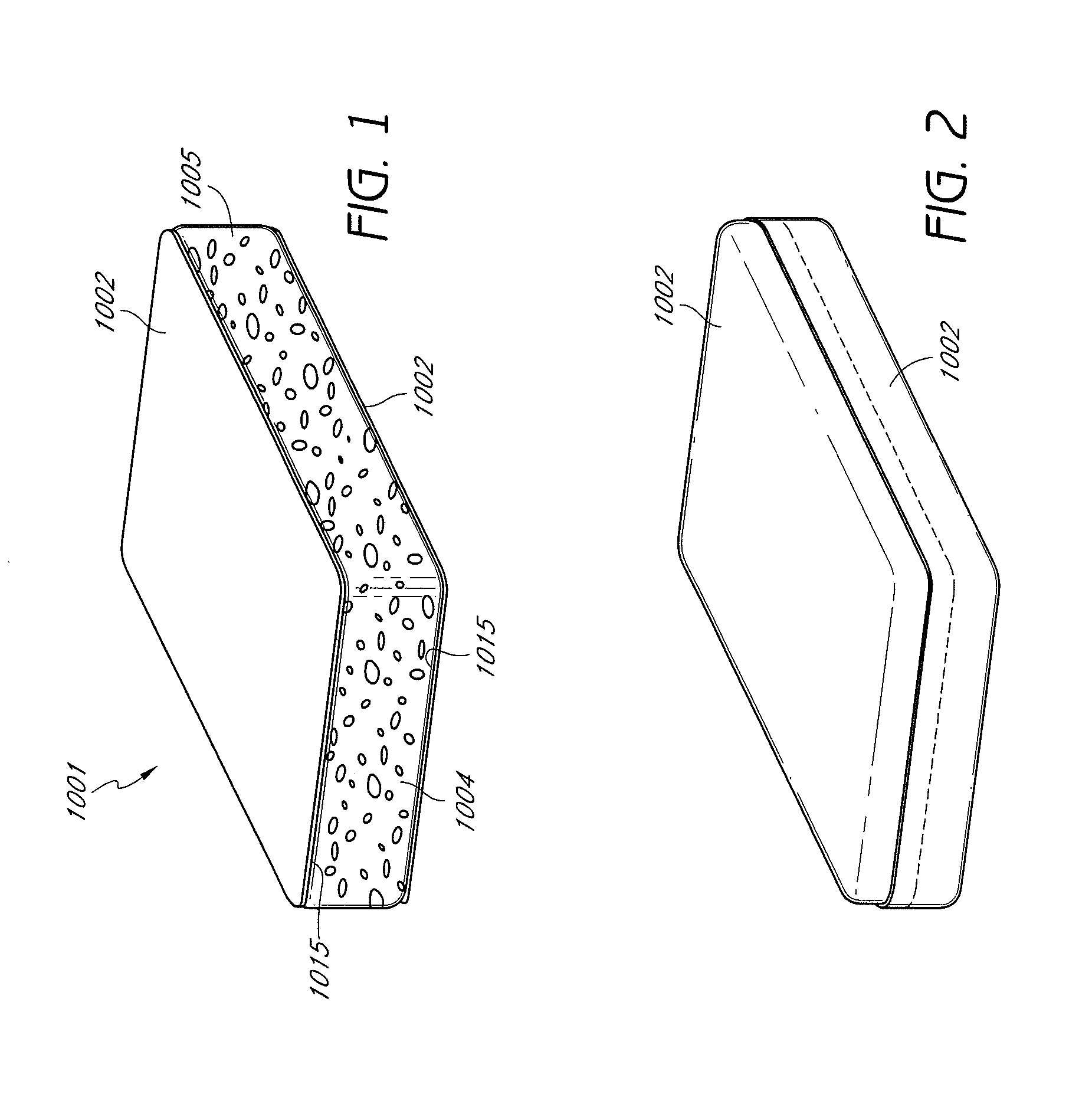
[0093]Referring to FIG. 1, disclosed is one embodiment of an implant 1001. The implant 1000 includes two layers of ePTFE 1002 which cover an inner element 1004. The ePTFE layer 1002 forms an outer layer which is exposed to native tissue. As such, the ePTFE layer 1002 provides desirable properties such as tissue ingrowth and biocompatibility. The implant 1001 may be shaped in any suitable manner depending upon the part of the body in which the implant 1001 is being used.

[0094]The inner element 1004 may be a porous and / or permeable material made of any suitable material such as an open cell silicone. Open cell structures and other features that can be used or modified for use with the implants and methods of use herein are described, for example, in U.S. patent application Ser. No. 12 / 024,835, filed Feb. 1, 2008 and hereby incorporated by reference in its entirety, particularly at FIGS. 1-31 and the accompanying description at paragraphs [0046] to [0061]. Furthermore, various features...


PUM

PropertyMeasurementUnit
Fractionaaaaaaaaaa
Fractionaaaaaaaaaa
Fractionaaaaaaaaaa

Abstract

The implant includes an outer layer of ePTFE which exhibits extensibility normally not associated with ePTFE. The ePTFE is reduced in length by deforming the fibrils between the nodes while maintaining the nodes in a substantially flat configuration. Various implant configurations that can include the outer layer described are also disclosed.

Description

[0001]The invention is directed to an implant and methods of forming an implant. In particular, the present invention is directed to methods and devices for making an implant covered by a porous layer of material such as expanded PTFE (ePTFE).BACKGROUND[0002]A problem which is encountered when using some porous materials such as ePTFE to cover an implant is that ePTFE can be relatively rigid and inelastic in one or more directions due to the inherent nature of many forms of ePTFE. As ePTFE is formed, numerous elongate fibrils are created which extend between nodes as the PTFE is stretched. The fibrils are often aligned with one another which provides high tensile strength when the ePTFE is tensioned in the direction of these fibrils. As such, the ePTFE has very little elasticity and is very stiff when tensioned in this direction. Consequently, a structure, such as an implant, which is covered with ePTFE may be somewhat stiff and may resist simple deformation due to this inelastic na...

Claims


Application Information

Patent Timeline
IPC IPC(8): A61F2/02B32B37/00
CPCA61L27/16A61L27/56A61L31/048A61L31/146B32B37/00C08L27/18
Inventor LESH, MICHAEL D.KUME, STEWARTKESTEN, RANDY J.CENTENO, LEOZALEWSKI, JEFF
Owner EVERA MEDICAL
Why Eureka
Try Eureka