Heat reflecting glass and process for producing heat reflecting glass

a technology of heat reflecting glass and heat reflecting glass, which is applied in the field of heat reflecting glass, can solve the problems of not meeting all the demands, the heat reflecting glass prepared by the process disclosed, etc., and achieve the effects of preventing heat from entering the room, preventing glare felt by a person, and preventing visible light transmittance tv

Inactive Publication Date: 2010-10-07
ASAHI GLASS CO LTD
View PDF5 Cites 11 Cited by
  • Summary
  • Abstract
  • Description
  • Claims
  • Application Information

AI Technical Summary

Benefits of technology

[0023]According to the present invention, it is possible to provide, for example, a heat reflecting glass which has a visible light transmittance Tv of at most 35% and a solar transmittance Te / visible light transmittance Tv ratio of less than 1.0 and of which the optical properties undergo substantially no change even if heat treatment is applied for strengthening or bending.
[0024]In other words, it is possible to provide a heat reflecting glass which can be heat-treated and of which the visible light transmittance Tv is sufficiently low to prevent glare felt by a person in a room in e.g. a building and to provide a privacy nature such that the inside is not seen from outside, and the solar transmittance Te / visible light transmittance Tv ratio is as low as less than 1.0 thereby to satisfy a performance to prevent heat from entering into the room.

Problems solved by technology

The heat reflecting glass prepared by the process disclosed in Patent Document 1 cannot satisfy all of the demands by the market in recent years.

Method used


Image

  • Heat reflecting glass and process for producing heat reflecting glass
  • Heat reflecting glass and process for producing heat reflecting glass
  • Heat reflecting glass and process for producing heat reflecting glass

Examples


example 1

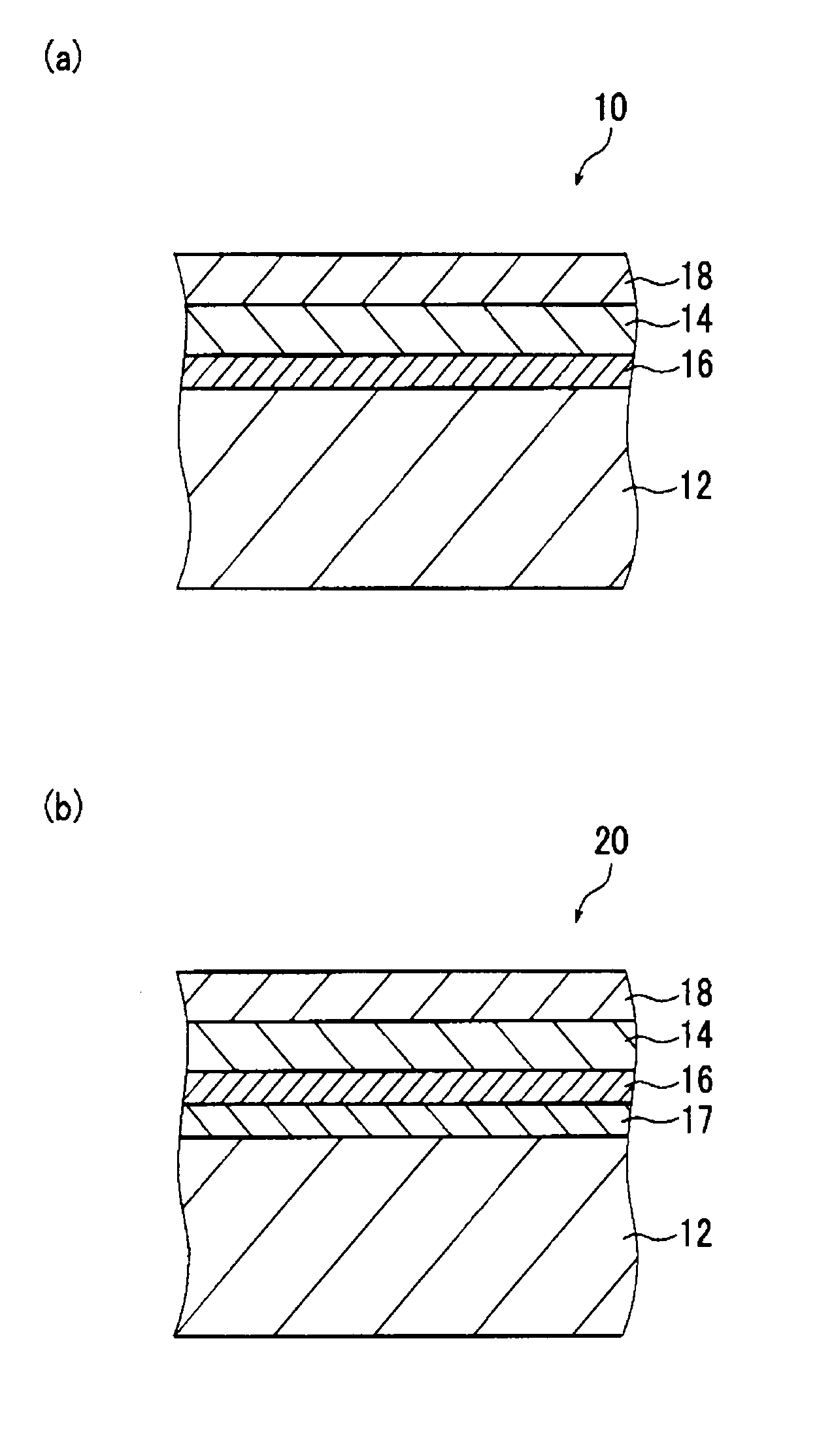
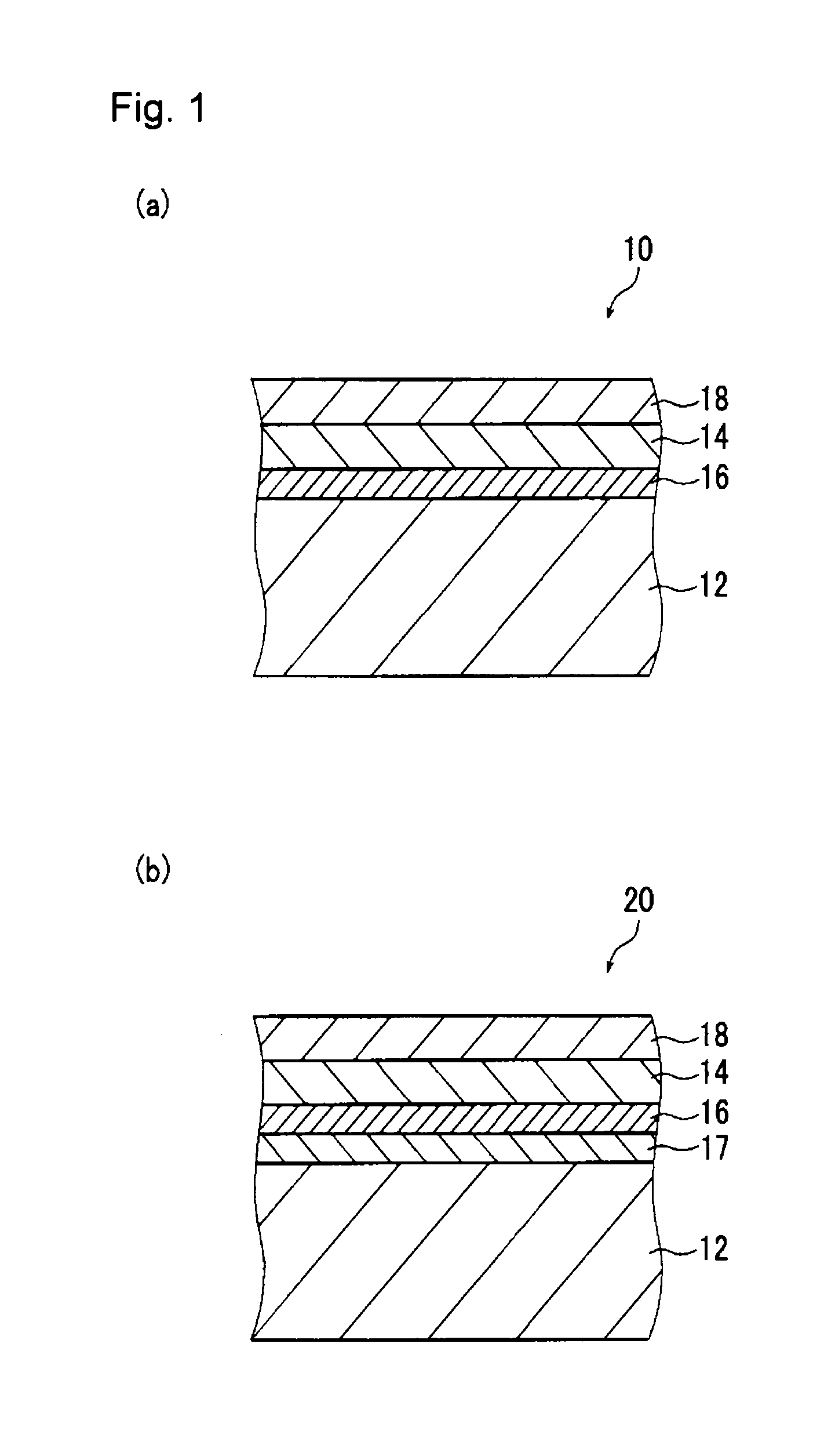
[0060]As Example 1, a heat reflecting glass corresponding to the first embodiment shown in FIG. 1(a) was prepared. Specifically, in Example 1, an oxygen-blocking undercoat film made of silicon nitride (SiNx) was formed on a glass substrate (FL6) by reactive sputtering, and as laminated on the surface of the oxygen-blocking undercoat film, a chromium nitride film was formed by reactive sputtering. Further, as laminated on the surface of the chromium nitride film, an oxygen-blocking protective film made of silicon nitride was formed.

[0061]The conditions at the time of forming the oxygen-blocking undercoat film and the oxygen-blocking protective film made of silicon nitride (SiNx), were as follows.[0062]Sputtering target: Polycrystalline Si target having a size of 130 mm×430 mm[0063]N2 gas flow rate during sputtering: 100 sccm[0064]Pressure in the chamber during sputtering: 5.1×10⁻¹ Pa[0065]Plasma-forming electric power: 2.00 kW as electric power supplied from a DC pulse power source

[0...

example 2

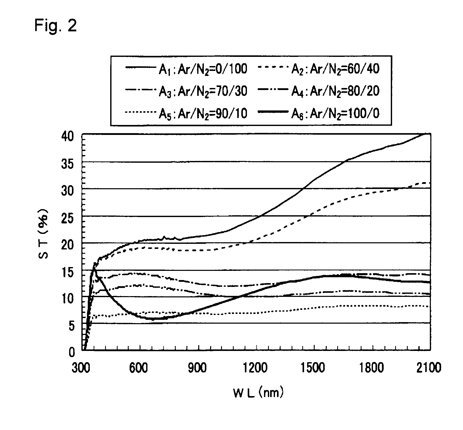
[0086]Firstly, the optical performance of a single chromium nitride (CrNx) film was examined as a Reference Example.

[0087]FIG. 2 is an example of results of tests carried out by the present inventors and shows spectra of spectral transmittances of a plurality of samples A1 to A5 constructed by preparing a single chromium nitride (CrNx) film on a glass substrate under respectively different film-deposition conditions. Each of the plurality of samples A1 to A5 is a sample obtained by preparing a chromium nitride film on the surface of a clean glass substrate (FL6) by a reactive sputtering method.

[0088]Each of chromium nitride (CrNx) single film samples A1 to A5 is a sample prepared in such a manner that a glass plate is disposed in a reactor (vacuum chamber) and sputtering is carried out by using a chromium (Cr) target as a sputtering target while the interior of the vacuum chamber is controlled to be a N2 gas-containing atmosphere, to form a chromium nitride film for heat reflection ...

example 3

[0113]Further, FIG. 6 shows the spectra of spectral transmittances of a plurality of samples D1 to D5 which were, respectively, formed by changing the film thickness of a chromium nitride film (CrNx) under a gas flow rate condition of (Ar:N2)=(80:20). Each of samples D1 to D5 is different only in the film thickness of each chromium nitride film (CrNx) from the film deposition conditions for sample C4. That is, each of samples D1 to D5 shown in FIG. 6 is prepared by setting the Ar gas flow rate / N2 gas flow rate to be (Ar:N2)═(80:20) and has a ratio in the number of atoms (N / Cr) in the chromium nitride film being 0.41. Further, the film thickness shown in the graph in FIG. 6 was obtained by a film deposition time preliminarily calculated from the measured value by using the preliminarily obtained film deposition rate.

[0114]As shown in FIG. 6, in a case where the ratio of nitrogen atoms to chromium atoms (N / Cr) in the chromium nitride film is substantially equal, even if the thickness ...


PUM

PropertyMeasurementUnit
visible light transmittanceaaaaaaaaaa
temperatureaaaaaaaaaa
thicknessaaaaaaaaaa

Abstract

To provide a heat reflecting glass provided with at least a chromium nitride film, which has a visible light transmittance Tv of at most 35% and a solar transmittance Te / visible light transmittance Tv ratio of less than 1.0 and which undergoes substantially no change in the optical properties even when subjected to heat treatment for strengthening or bending. An oxygen-blocking undercoat film made of silicon nitride is formed on the surface of a glass substrate; a chromium nitride film for heat reflection is formed as an upper layer of the oxygen-blocking undercoat film; and further, an oxygen-blocking protective film made of silicon nitride is formed as an upper layer of the chromium nitride film. The ratio in the number of atoms of nitrogen to chromium in the chromium nitride for heat reflection is from 20% to 60%.

Description

TECHNICAL FIELD[0001]The present invention relates to a heat reflecting glass having at least a chromium nitride film formed on a glass substrate. Particularly, it relates to a heat reflecting glass having a thin film formed on the surface of a glass substrate for the main purpose of blocking solar radiation heat, and a process for producing such a heat reflecting glass.BACKGROUND ART[0002]At present, a heat reflecting glass having a thin film formed on the surface of a glass substrate for the main purpose of blocking solar radiation heat, is used for e.g. a window of architectural structures such as buildings, or as a rear glass for vehicles. From a viewpoint of a light transmitting property of such a heat reflecting glass, a demand for a heat reflecting glass having a low transmittance is also increasing. In a case where a glass is used for a window of architectural structures such as buildings, depending upon the site where the glass is to be installed, strengthening treatment is...

Claims


Application Information

Patent Timeline
Patent Type & Authority Applications(United States)
IPC IPC(8): B32B17/06C23C14/34C23C14/10
CPCC03C17/3435C03C17/366C03C2218/154Y10T428/265C23C14/0641C23C14/0652Y02T50/67C23C14/0036Y02T50/60
Inventor YAOITA, KAZUYAKATAYAMA, YOSHIHITO
Owner ASAHI GLASS CO LTD
Why Eureka
Try Eureka