Real-time, active picometer-scale alignment, stabilization, and registration in one or more dimensions

a picometer-scale, real-time technology, applied in the direction of calibration apparatus, instruments, optical radiation measurement, etc., can solve the problems of laser noise, art with drift, subsequently be some drift, etc., to achieve constant alignment and separation, high bandwidth, and yield picometer-scale precision and stability.

Inactive Publication Date: 2010-10-07
THE UNITED STATES OF AMERICA AS REPRESENTED BY THE SECRETARY OF THE COMMERCE
View PDF5 Cites 22 Cited by
  • Summary
  • Abstract
  • Description
  • Claims
  • Application Information

AI Technical Summary

Benefits of technology

[0061]Here, a real time differential measure of the substrate surface and patterning mask can be enabled by monitoring scattering from fiducial marks on both elements. In one embodiment used for a typical projection lithography process, one laser beam is incident upon the imaging lens from below and exposure radiation is incident from above. For the purpose of this example, the substrate is situated above a lens and the mask is situated above the substrate. The laser beam from below would focus on the fiducial mark of the substrate and this laser (or a second laser beam) could interact with the fiducial mark in the mask. As described previously, the scattered light could be detected either with forward or backscattered detection and electronically processed. The position of one (or both) structures can then be varied so as to maintain a constant alignment and separation in one or more dimensions (e.g. x, y, & z) during the exposing processing step(s). This position can also be scanned precisely as is typical in stepping lithography. For multiple layer processes, the fiducial marks can be aligned accurately by iteratively scanning the position of both structures. Importantly, all alignment, stabilization and registration methods described here are high bandwidth active processes which can yield picometer-scale precision and stability even in the presence of external fluctuations (e.g., temperature fluctuations, mechanical vibrations and acoustic noise).

Problems solved by technology

There is a problem in the art with drift.
In fields such as optical microscopy and semiconductor characterization, where it is highly desirable to achieve accurate positioning and stabilization, there has been a long-standing problem with various methods of alignment and stabilization, particularly for mechanically independent structures.
Typically, after positioning and aligning two structures relative to each other, there will subsequently be some drift (e.g. due to thermal expansion of the microscope's body).
Moreover, since most optical microscopes have a tendency to be more sensitive to drift prior to magnification, it is the motion of the objective relative to the sample that is typically the major source of drift.
In laser-based tracking methods, apparent drift can further be caused by laser noise.
Various types of noise adversely impact aligning and stabilizing methods.
For example, there are known problems with pointing noise, intensity noise, polarization noise and mode noise.
To reiterate, all of these types of noise have adversely impacted alignment, stabilization and registration.
Additionally, the lateral oscillation (typical amplitude 0.5 nm) reduces microscope resolution.
There are also problems achieving stabilization with an Atomic Force Microscope (AFM).
In the prior art, there are known problems aligning and stabilizing the tip relative to the sample.
However, dithering the probe has drawbacks because it sacrifices resolution and only gives a relative position as opposed to an absolute position.
Accordingly, as the measurements resolve ever decreasing distances, there is an increase in the criticality of unwanted physical drift.
While such stages have an effective internal measurement of the position of their drift (about a nanometer) in three dimensions, they do not compensate for drift caused from thermal expansion between the sensors and the sample plane.
This does not provide a local measurement of drift.
This technique is computationally intensive and requires the image plane to be defocused so that diffraction rings can be observed.
However, this technique, in addition to being computationally intensive, also requires post-processing of the data, thus preventing real-time stabilization.
Moreover, the placing of fiducial marks was not practical.

Method used


Image

  • Real-time, active picometer-scale alignment, stabilization, and registration in one or more dimensions
  • Real-time, active picometer-scale alignment, stabilization, and registration in one or more dimensions
  • Real-time, active picometer-scale alignment, stabilization, and registration in one or more dimensions

Examples


Embodiment Construction

[0071]It is understood by a person of ordinary skill in the art that the drawings are presented for purposes of illustration and not for limitation. The embodiments shown and described herein do not encompass all possible variations of the arrangement of structure or the type of substances that can be quantified thereby. Therefore, an artisan appreciates that many modifications can be made within the spirit of the invention and the scope of the appended claims than the illustrative examples shown and described.

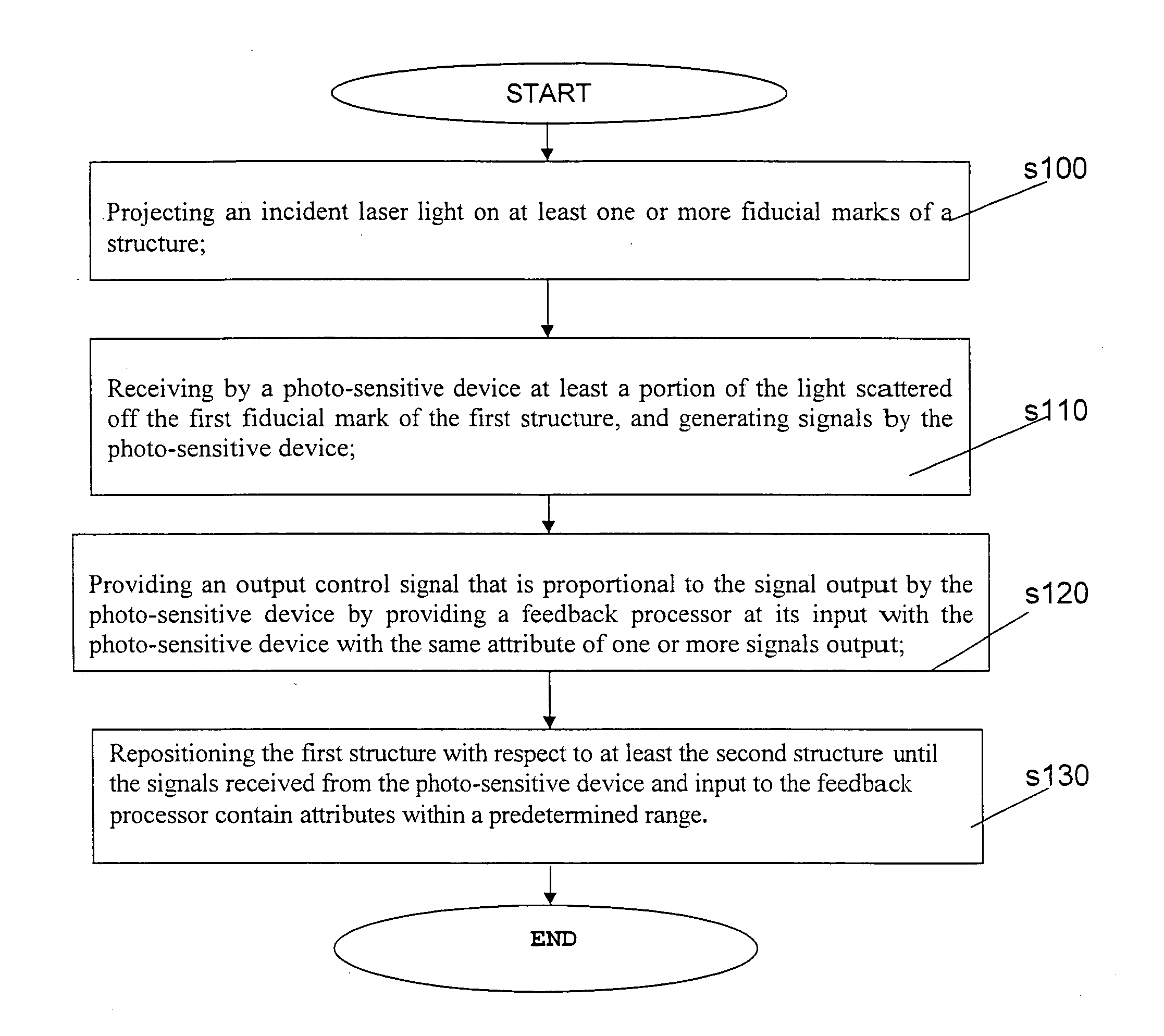
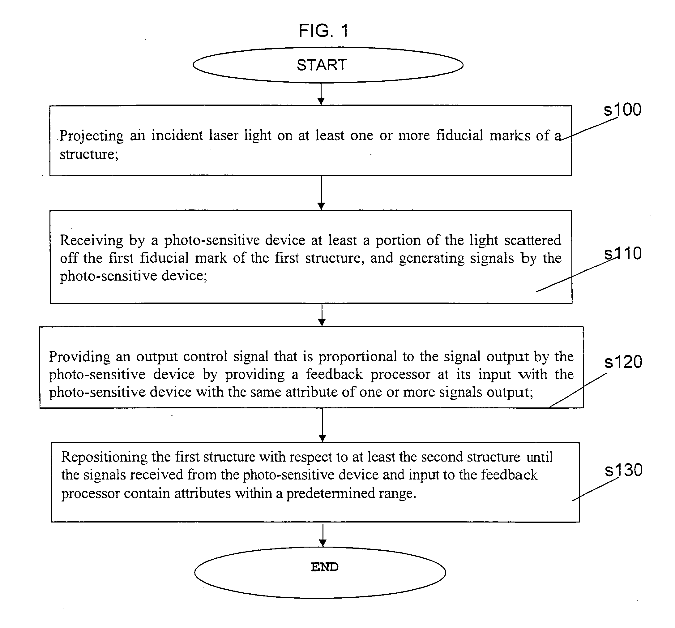
[0072]FIG. 1 provides an overview of a method of aligning two or more mechanically independent structures in time according to the present invention. At step 100, positioning two or more mechanically independent structures that are marked with at least one fiducial mark on each structure. At step 110, scattering a laser light beam against the at least one fiducial mark. At step 120, a photo-sensitive device positioned relative to the independent structures reads the scattered ...


PUM


Abstract

A method and apparatus for aligning, stabilizing and registering two or more structures in one or more dimensional space with picometer-scale precision. Low noise laser light is scattered by at least one or more structure or fiducial marks. One mark may be coupled to each structure to be positioned. The light which has been scattered off the fiducial marks is collected in a photo-sensitive device which enables real-time high-bandwidth position sensing of each structure. One or more of the structures should be mounted on a stage, and the stage can move in either one or more dimensions. The photo-sensitive device generates signals in response to the scattered light received, and the signals are used to modulate the position of the stage in a feedback loop.

Description

[0001]This application claims priority from provisional application 60 / 725,203 filed Oct. 11, 2005, and the contents of which are incorporated by reference in its entirety.BACKGROUND OF THE INVENTION[0002]1. Field of the Invention[0003]The present invention relates to the use of light to position and stabilize structures, including but not in any way limited to the fields of scanning probe microscopy, Atomic Force Microscopy (AFM), optical microscopy, local probe lithography, semiconductor patterning including semi-conductor wafer and mask alignment, and operating optical tweezers. More particularly, the present invention relates to the use of real-time alignment and stabilization of structures at a picometer-scale level.[0004]2. Description of the Related Art[0005]There is a problem in the art with drift. In fields such as optical microscopy and semiconductor characterization, where it is highly desirable to achieve accurate positioning and stabilization, there has been a long-stan...

Claims


Application Information

Patent Timeline
Patent Type & Authority Applications(United States)
IPC IPC(8): G01Q10/00G12B13/00
CPCB82Y35/00G01Q10/065G01Q40/02
Inventor PERKINS, THOMAS T.KING, GAVIN M.CARTER, ASHLEY R.
Owner THE UNITED STATES OF AMERICA AS REPRESENTED BY THE SECRETARY OF THE COMMERCE
Why Eureka
Try Eureka