Microfluidic devices and methods of preparing and using the same

US20100261286A1Inactive Publication Date: 2010-10-14NANO DITECH CORP

Image

  • Microfluidic devices and methods of preparing and using the same
  • Microfluidic devices and methods of preparing and using the same
  • Microfluidic devices and methods of preparing and using the same

Examples


Embodiment Construction

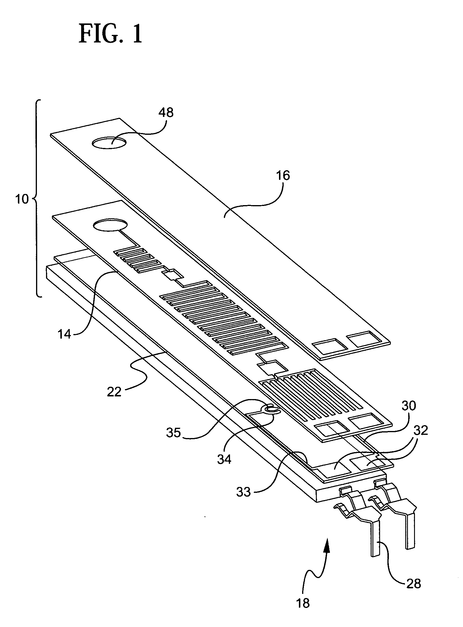
[0053]Referring to the accompanying drawings wherein like reference numbers refer to the same or similar elements, an embodiment of a microfluidic device in accordance with the invention is shown in FIG. 1 and designated generally as 10. Microfluidic device 10 includes a support 22, a photoresist layer 14 arranged above the support 22, a cover layer 16 arranged above the photoresist layer 14 and an electrical interconnection unit 18 arranged in connection with the support 22.

[0054]Support 22 forms or is part of a support structure for microfluidic device 10 which can take any form which provides a preferably rigid underlying substrate for the photoresist layer 14. The support structure can include a base, a substrate, and a layer of material, either alone or various combinations thereof. In the illustrated embodiment, the support structure includes a rigid backing substrate 20 which provides strength and rigidity to the microfluidic device 10 and the support 22 which is a first PET ...


PUM


Abstract

Microfluidic devices include a photoresist layer in which an inlet chamber, an optional reaction chamber and at least one detection chamber are in fluid contact, a support arranged under the photoresist layer and a cover arranged above the photoresist layer. The devices further include a set of absorbent channels downstream of the last detection chamber. Biogenic or immunoreactive substances are placed in the reaction chamber and detection chamber(s). When a liquid sample is dropped into the inlet chamber, the sample liquid is drawn through the devices by capillary action. Detection methods include electrochemical detection, colorimetric detection and fluorescence detection.

Description

CROSS-REFERENCE TO RELATED APPLICATIONS[0001]This application claims the benefit of priority from U.S. Provisional Application Ser. No. 60 / 699,580 filed Jul. 14, 2005, the contents of which are incorporated herein by reference.FIELD OF THE INVENTION[0002]The field of the invention relates generally to microfluidic devices, fabrication methods for microfluidic devices and the use of microfluidic devices in biological assays.BACKGROUND OF THE INVENTION[0003]Point of care tests, i.e., tests which are performed at the point of care (POC), have become common diagnostic tools used in hospitals, doctors' offices, workplaces, and potentially hostile environments. Tasks such as workplace testing for drug abuse, environmental testing for pollutants, and testing for bio-warfare agents on the battlefield can be simply and easily performed with point of care tests. Since the tests are often performed by individuals having little, if any, clinical diagnostics training, point of care tests need to...

Claims


Application Information

Patent Timeline
14 Oct 2010
Publication
US20100261286A1
IPC
G01N27/419; G01N30/00; G01N27/22; G01N21/00; G01N27/26
CPC
B01L3/502707; B01L2200/12; B01L2300/0636; B01L2300/0645; B01L2300/069; B01L2300/0816; B82Y40/00; B01L2300/0867
Inventors
KIM, YOUNG HOON; SON, MUNTAK