Optical transmitter module and optical bi-directional module with function to monitor temperature inside of package and method for monitoring temperature

Inactive Publication Date: 2010-10-21
SUMITOMO ELECTRIC IND LTD
View PDF3 Cites 11 Cited by
  • Summary
  • Abstract
  • Description
  • Claims
  • Application Information

AI Technical Summary

Benefits of technology

[0011]The optical module of the invention may further enclose in the CAN package a receiver PD, a pre-amplifier and an optical filter. The LD may emit the signal light with the first wavelength to an external fiber, while, the receiver PD may receive another signal light with the second wavelength different from the first wavelength from the external fiber. The optical filter may reflect the signal light, while, may transmit the other signal light. The receiver PD and the pre-amplifier may be operated based on a receiver ground, while, the LD is operated based on a transmitter ground that is electrically isolated from the receiver ground. In the presen

Problems solved by technology

However, continuous request to make the package of the optical

Method used


Image

  • Optical transmitter module and optical bi-directional module with function to monitor temperature inside of package and method for monitoring temperature
  • Optical transmitter module and optical bi-directional module with function to monitor temperature inside of package and method for monitoring temperature
  • Optical transmitter module and optical bi-directional module with function to monitor temperature inside of package and method for monitoring temperature

Examples


first embodiment

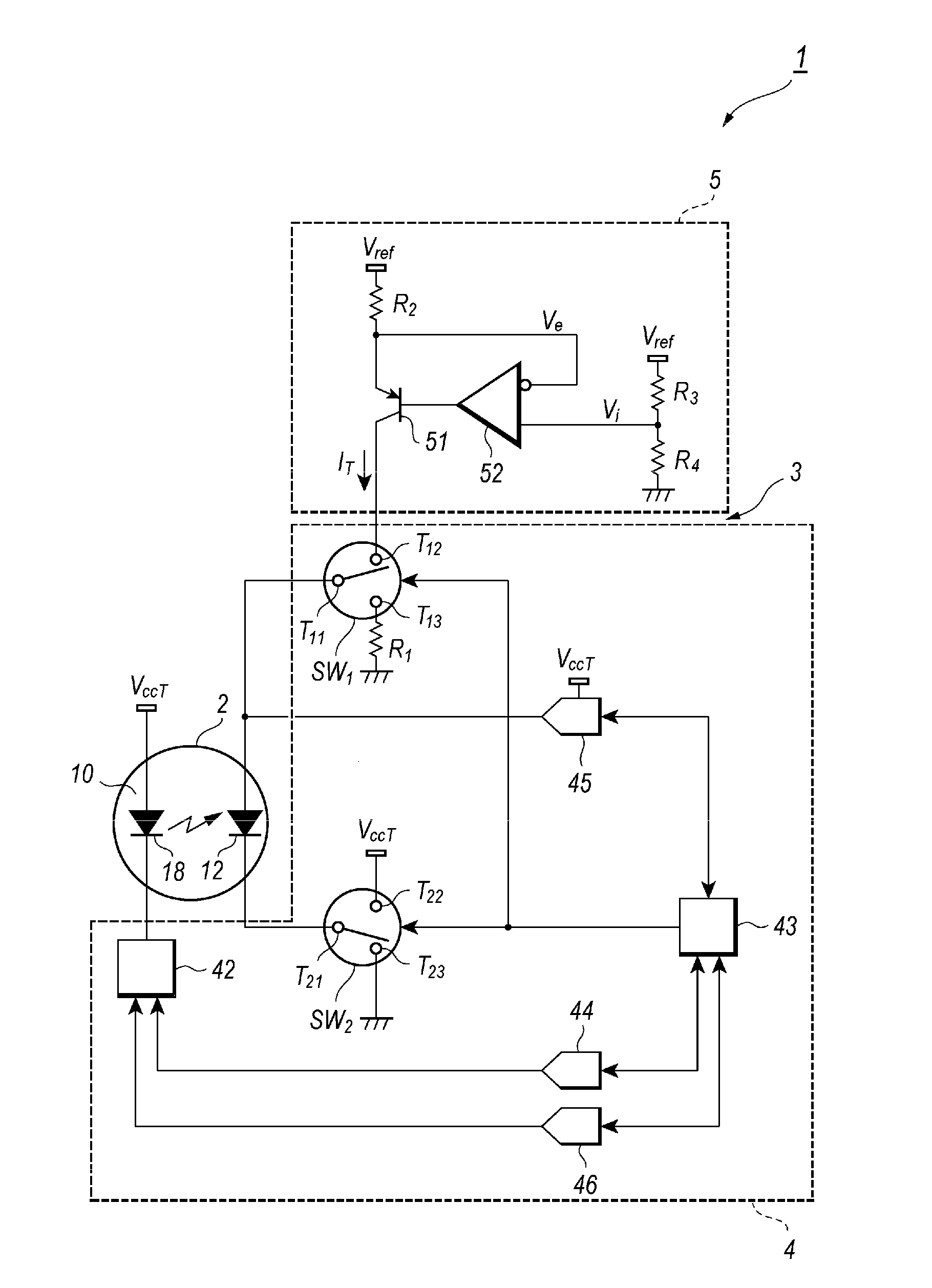
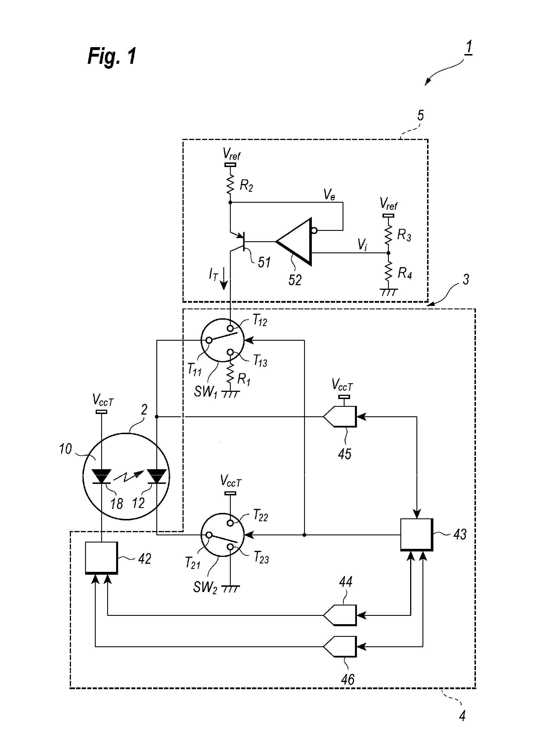
[0026]FIG. 1 is a block diagram of an optical module 1 according to an embodiment of the present invention. The optical module 1 comprises an optical assembly 2 including an optical transmitter and a circuit 3 to control the optical assembly 2. The optical transmitter has a semiconductor LD 18 and a monitor PD 12 that monitors a portion of signal light output from the LD 18, where the LD 18 and the monitor PD 12 are assembled within a CAN type package 10.

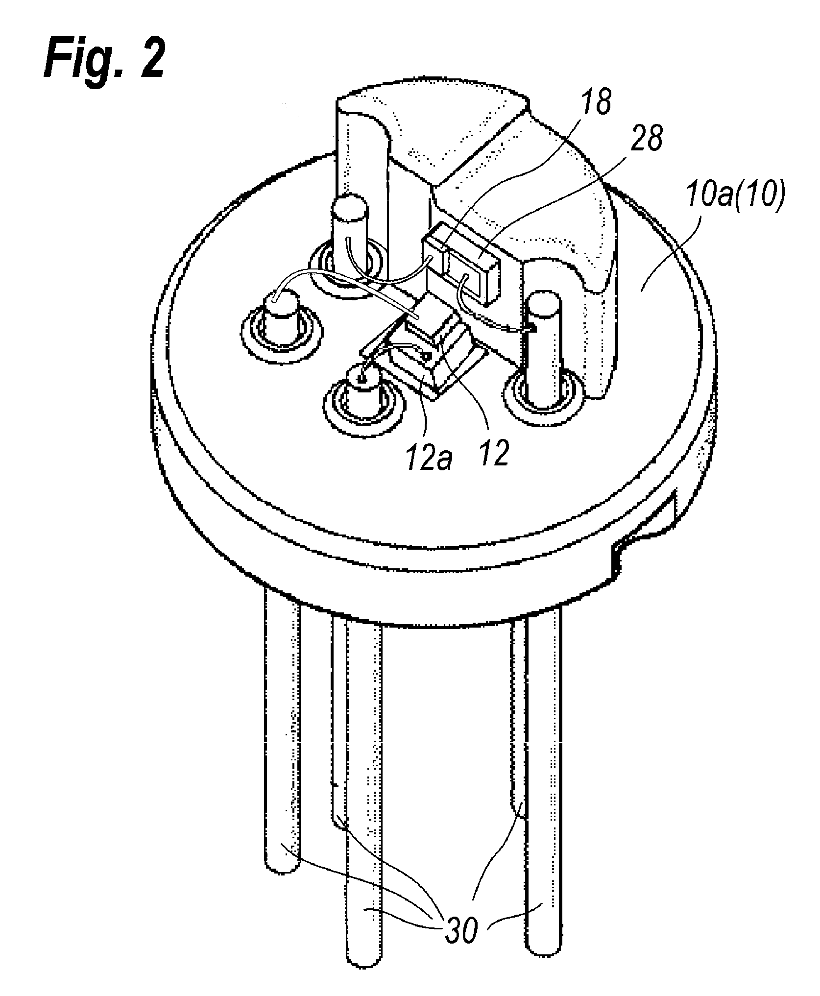
[0027]FIG. 2 illustrates a typical arrangement within the CAN package 10 of the optical assembly 2. The CAN package 10 of the optical assembly 2 includes a disk shaped stem 10a and a cap, which is not illustrated in FIG. 2, attached to a periphery of the stem 10a so as to form a space in which devices such as LD 18 and the monitor PD 12 are hermetically enclosed. On the stem 10a is assembled with the LD 18 and the monitor PD 12 through a PD sub-mount 12a so as to receive light emitted from the back facet of the LD 18. The LD is moun...

second embodiment

[0042]FIG. 5 illustrates a circuit diagram of an optical module 1a according to the second embodiment of the invention. The optical module shown in FIG. 5 includes, compared with the optical module 1 shown in FIG. 1, a modified optical assembly 2a and a modified control circuit 4a. The optical assembly 2a of the embodiment further includes a receiver photodiode 20 and a pre-amplifier 22 in the common package 10. The receiver PD 20 may be a type of avalanche photodiode (hereafter denoted as APD) with a carrier multiplying function, while the pre-amplifier 22 converts a photocurrent generated in the APD 20 in to a voltage signal and amplifies this voltage signal to output from the optical assembly 2a.

[0043]FIG. 6 illustrates the inside of the CAN package 10 of the optical assembly 2a. As shown in FIG. 2a, the CAN package includes a disk shaped stem 10a and a cap 10b attached to a periphery of the stem 10a so as to form a space in which the devices like the LD 18, the monitor PD 12 an...


PUM


Abstract

An optical module with a function to monitor a temperature within the package without installing any specific temperature sensing device is disclosed. The optical module of the invention includes an LD and a monitor PD in a CAN type housing. When the LD is inactive or driven under a constant bias current, the monitor PD receives a constant current independent of the temperature. The forward voltage of the monitor PD indicates the temperature within the package.

Description

BACKGROUND OF THE INVENTION[0001]1. Field of the Invention[0002]The present invention relates to an optical module, in particular, the invention relates to a transmitter optical module and a bi-directional optical module with a function to monitor a temperature inside of a package without implementing a specific temperature sensing device, and the invention relates to a method to sense a temperature inside of the package.[0003]2. Related Prior Art[0004]The emission of a semiconductor laser diode (hereafter denoted as LD) applied to the optical communication system strongly depends on an operating temperature, which is generally called as the temperature dependence of the I-L characteristic. An LD shows a smaller threshold current ITH and a larger slope efficiency η in relatively lower temperature, while, they degrades in higher temperatures, that is, the threshold current ITH increases and the slope efficiency η decreases. Accordingly, the bias current Ib and the modulation current ...

Claims


Application Information

Patent Timeline
IPC IPC(8): G08B17/00
CPCH01S5/0683H01S5/06804H01S5/02212
Inventor ICHINO, MORIYASUMIKI, TAKAHIROHASEGAWA, YOSHIMICHIUKAI, TORU
Owner SUMITOMO ELECTRIC IND LTD
Why Eureka
Try Eureka