Microchip and blood monitoring device

Active Publication Date: 2010-10-21
FUJIMORI KOGYO CO LTD
View PDF15 Cites 33 Cited by
  • Summary
  • Abstract
  • Description
  • Claims
  • Application Information

AI Technical Summary

Benefits of technology

[0092]In the microchip of the present invention according to claim 1, inclusion of a stirring bar for mixing the first liquid and the second liquid in the merged channel allows stirring and mixing uniformly the first liquid and the second liquid in the mixing section of the microchip while suppressing activation of blood coagulation which leads to occurrence of a blood coagulation clot or the like, so that the microchip of the present invention according to claim 1 is suitable for monitoring, for example, blood coagulation and platelet function using a liquid containing whole blood, platelet-rich plasma or a drug-treated liquid thereof or the like.
[0093]In the microchips of the present invention according to claims 2 and 3, in cases where the coagulation inhibition treatment for inhibiting coagulation of the liquid produced by confluence of the first liquid and the second liquid is a treatment by which at least the surface of the stirring bar is formed with heparin, polyvinyl lactonamide or poly(2-methoxyethyl acrylate), the stirring bar can be prepared by coating by soaking in a molten resin or resin finishing such as injection molding, and therefore the microchips can be efficiently prepared.
[0094]In the microchip of the present invention according to claim 4, since the width of the stirring section is larger than that of the merged channel, the liquid produced by confluence of the first liquid and the second liquid can be ma

Problems solved by technology

In atherothrombosis such as myocardial infarction, atherosclerotic plaque collapses at the site of arteriosclerosis, and platelets adhere to collagen containing tissue factor which was exposed to the blood flow, followed by complex occurrence of platelet aggregation and activation of the blood coagulation system, leading to formation of a serious occlusive thrombus.
However, in myocardial infarction and the like, formation of a thrombus proceeds only in areas of arteriosclerosis, and the thrombotic tendency does not extremely proceed throughout the body.
However, a thrombus grows under blood flow in vivo, and since the above-described monitoring method and the like are those carried out in a closed in vitro system, it is impossible to observe a state wherein a thrombus grows in vivo.
Further, in cases where platelets were stained with quinacrine by the method according to Patent Literature 1 or Non-patent Literature 1 or 2, leukocytes were also stained at the same time, so that selective evaluation of only the function of platelets was impossible.
Further, there were many points unsuitable for the monitoring, such as color deterioration of the fluorescent dye and e

Method used


Image

  • Microchip and blood monitoring device
  • Microchip and blood monitoring device
  • Microchip and blood monitoring device

Examples


example 1

[Preparation of Microchip and Blood Monitoring Device]

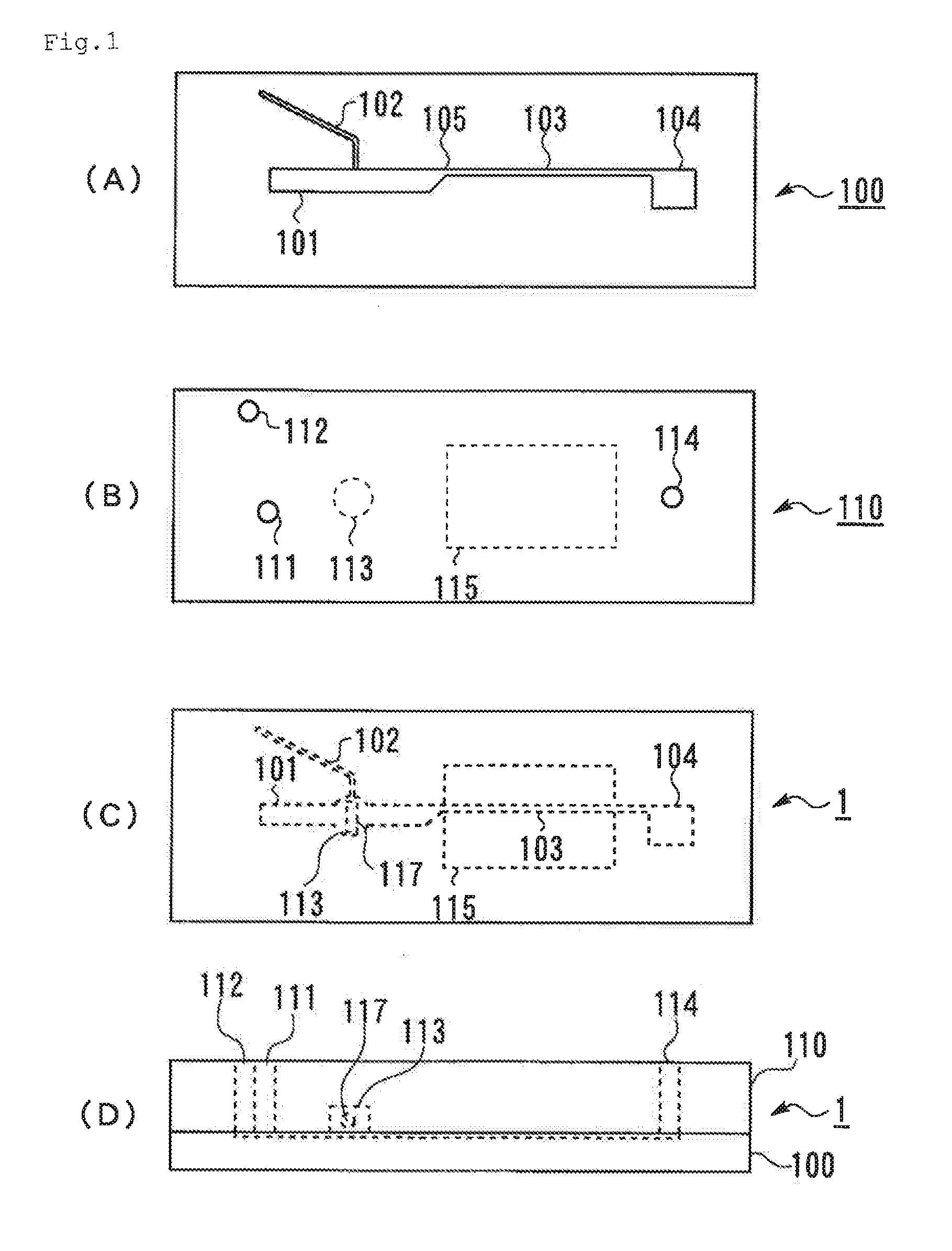
[0224]Two transparent substrates, that is, the first substrate 100 shown in FIG. 1A and the second substrate 110 shown in FIG. 1B (injection-molded products manufactured by Richell Corporation) were prepared. The first substrate 100 and the second substrate 110 were laminated with each other using an adhesive such that the side of the first substrate 100 where the channels open and the side of the second substrate 110 where the hole constituting the stirring section 113 opens face to each other, to provide the microchip 1 shown in FIG. 1C and FIG. 1D. The depth of each channel was 0.12 mm, the width of the first channel 101 was 1.2 mm, and the width of the narrowing section of the merged channel 103 was 0.3 mm. As the stirring bar 117, an iron cylinder coated with PVLA, having a diameter of 1 mm and a length of 2 mm was placed in the stirring section 113. The hole constituting the stirring section 113 was a penetrating hole whose...

example 2

[Preparation of Microchip]

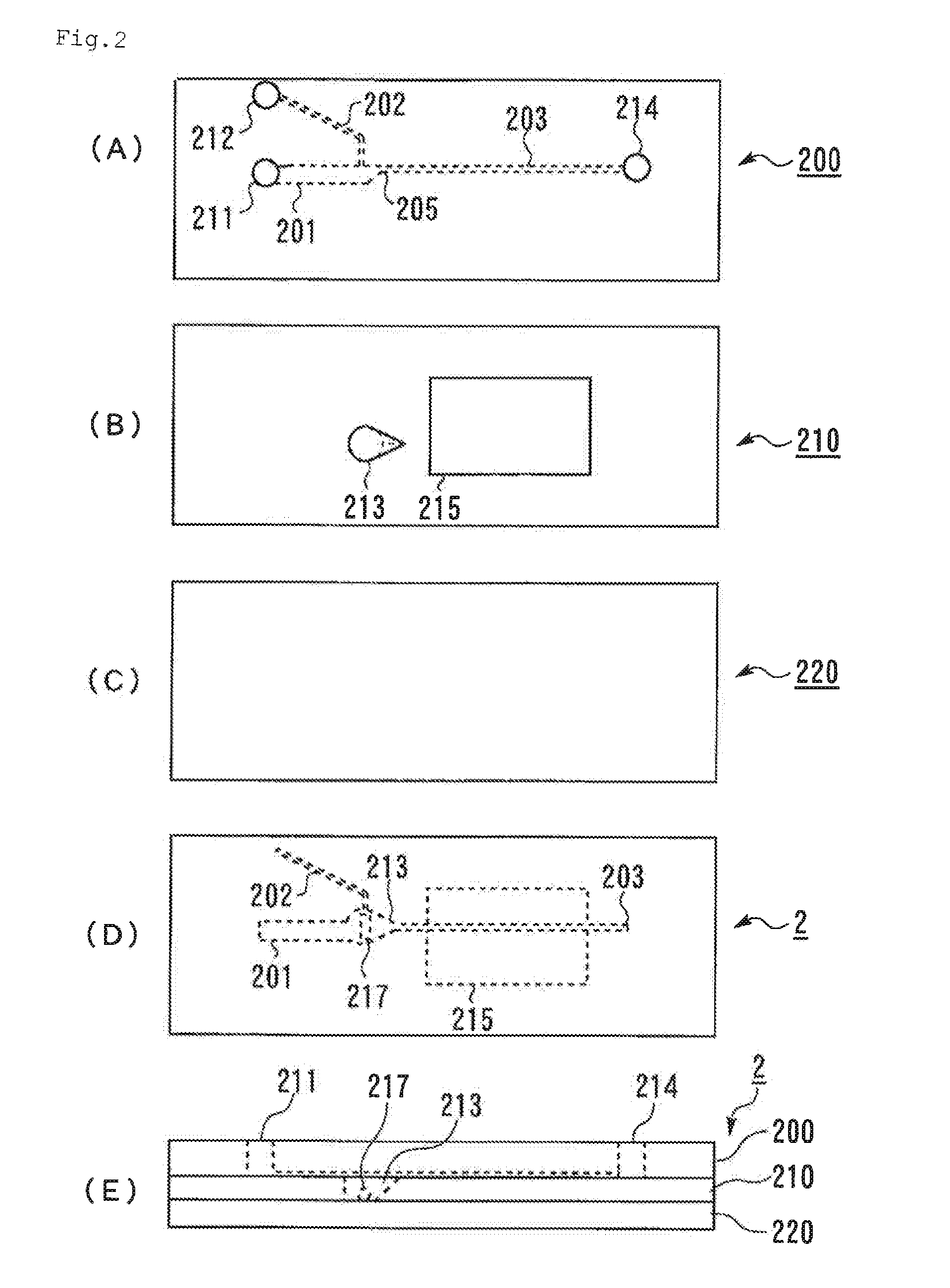
[0229]Two transparent substrates, that is, the first substrate 200 shown in FIG. 2A and the second substrate 210 shown in FIG. 2B (injection-molded products manufactured by Fluidware) and the third substrate 220 shown in FIG. 2C which is a transparent acrylic plate were prepared. The first substrate 200 and the second substrate 210 were laminated with each other using an adhesive such that the side of the first substrate 200 where the channels open and the side of the second substrate 210 where the hole constituting the stirring section 213 opens face to each other. The opening of the hole of the stirring section 213 of the second substrate 200 was closed by the third substrate 220 using an adhesive, to provide the microchip 2 shown in FIG. 2D and FIG. 2E. The thickness of the second substrate 210 was 1.2 mm, which thickness corresponded to the depth of the hole constituting the stirring section 213. The shape of the hole constituting the stirring section 2...

example 3

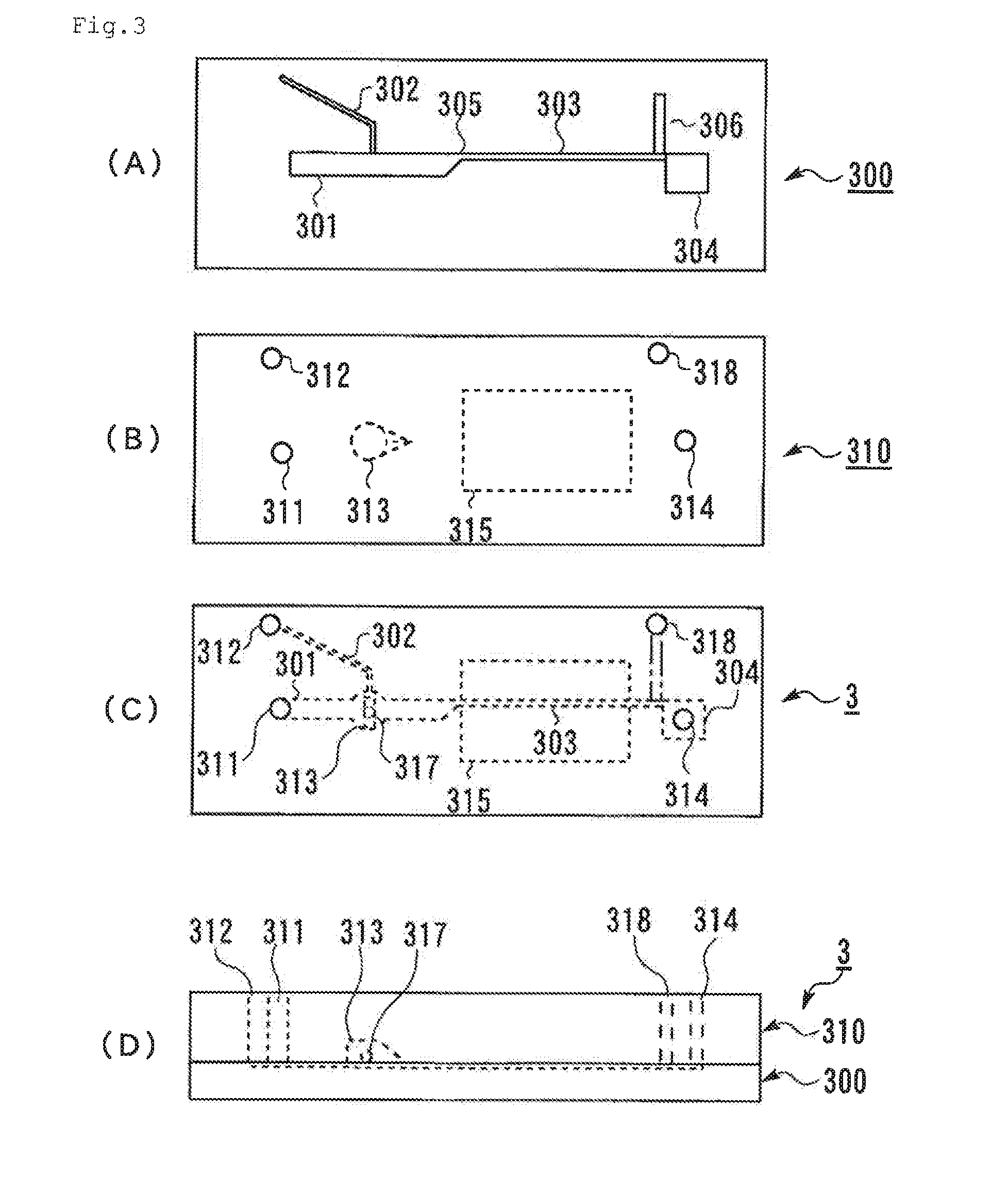
[0232]The microchip 2 and a blood monitoring device were prepared in the same manner as in Example 2 except that the stirring section 213 of the second substrate 210 in Example 2 was simply a circular penetrating hole having an inner diameter of 3 mm. Experiments to confirm the state of mixing were carried out in the same manner as in Example 2. As a result, the two liquids were uniformly mixed with each other, but in some cases, air remained in the stirring section.


PUM


Abstract

A microchip comprising therein a first channel which allows inflow of a first liquid selected from whole blood, platelet-rich plasma and a drug-treated liquid thereof, a second channel connected to the first channel, which allows inflow of a second liquid containing an agent that is reactive with the first liquid, and a merged channel extended from the connection portion of the first channel with the second channel, wherein, in the merged channel, a stirring section having a stirring bar for mixing the first liquid with the second liquid is provided; and a blood monitoring device using the same.

Description

TECHNICAL FIELD[0001]The present invention relates to a chip for efficiently mixing a small amount of blood with an agent to analyze the reactivity and properties of the blood, more particularly, a microchip for blood monitoring such as monitoring of blood coagulation capacity and platelet function, and a blood monitoring device using it.BACKGROUND ART[0002]In atherothrombosis such as myocardial infarction, atherosclerotic plaque collapses at the site of arteriosclerosis, and platelets adhere to collagen containing tissue factor which was exposed to the blood flow, followed by complex occurrence of platelet aggregation and activation of the blood coagulation system, leading to formation of a serious occlusive thrombus. Heart diseases such as myocardial infarction are serious diseases which represent the second commonest cause of death among all of the causes of death in Japan.[0003]However, in myocardial infarction and the like, formation of a thrombus proceeds only in areas of arte...

Claims


Application Information

Patent Timeline
IPC IPC(8): C12Q1/56C12M1/34
CPCA61B5/14546B01F5/0646B01F5/0654G01N33/4905B01L3/5027G01N1/38B01F13/0059B01F25/4337B01F25/433B01F33/30
Inventor HOSOKAWA, KAZUYAWADA, TOMOKO
Owner FUJIMORI KOGYO CO LTD
Why Eureka
Try Eureka