Photoacoustic imaging devices and methods of imaging

a technology of photoacoustic imaging and imaging modules, applied in the field of photoacoustic imaging modules and methods, to achieve the effects of improving image contrast, rapid thermal-elastic expansion process, and reducing voltage and power

Active Publication Date: 2010-10-21
STC UNM
View PDF12 Cites 62 Cited by
  • Summary
  • Abstract
  • Description
  • Claims
  • Application Information

AI Technical Summary

Benefits of technology

[0016]The present disclosure relates to photoacoustic imaging modules for medical diagnosis. When tissue is stimulated with infrared light, the imaging module generates ultrasound through a rapid thermal-elastic expansion process. An array of ultrasonic transducers, which can be capacitive micromachined ultrasonic transducers (CMUT) or piezoelectric transducers, may be used to receive the ultrasound transmitted from the tissue. The infrared light for photoacoustic imaging may be provided via an array of light sources along the peripheral of this module, which can be an array of near-infrared laser diodes, light emitting diodes, or optical fibers (with connection to external light sources) mounted inside tilted recesses distributing along the peripheral of the frame. The module may be integrated into a wireless endoscope to create an internal imaging device that delivers better image contrast and operates at lower voltage and power. This device may therefore operate with a battery for a longer time.

Problems solved by technology

This device may therefore operate with a battery for a longer time.

Method used


Image

  • Photoacoustic imaging devices and methods of imaging
  • Photoacoustic imaging devices and methods of imaging
  • Photoacoustic imaging devices and methods of imaging

Examples


Embodiment Construction

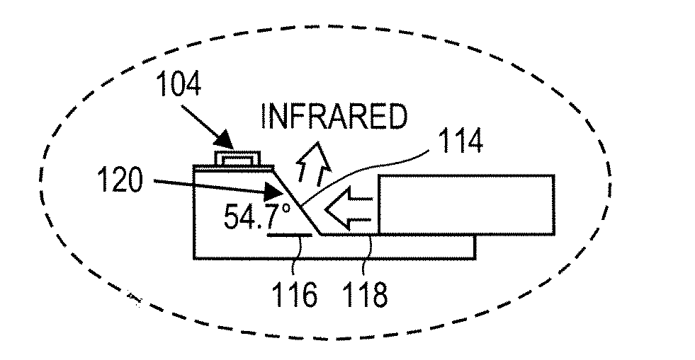
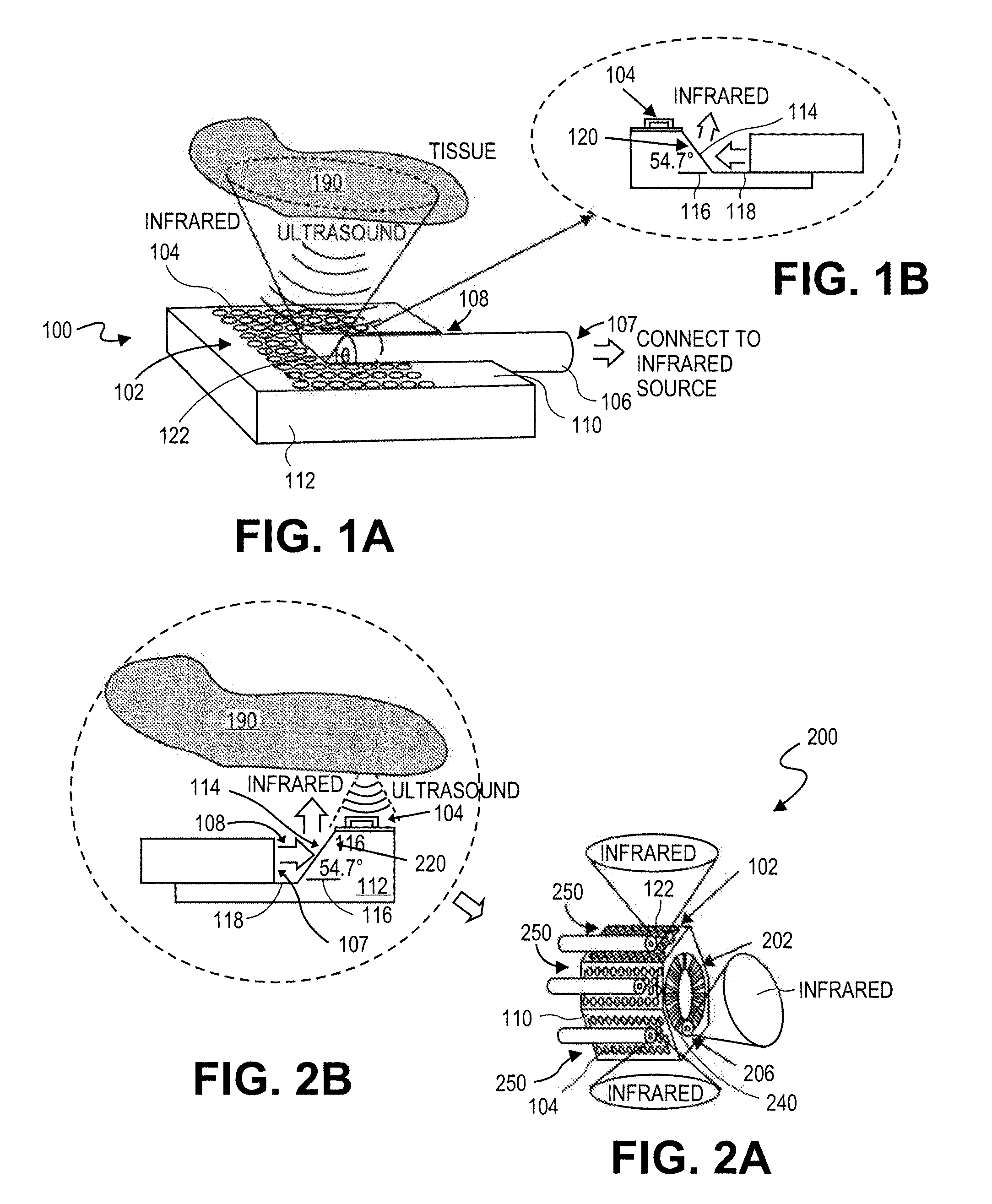
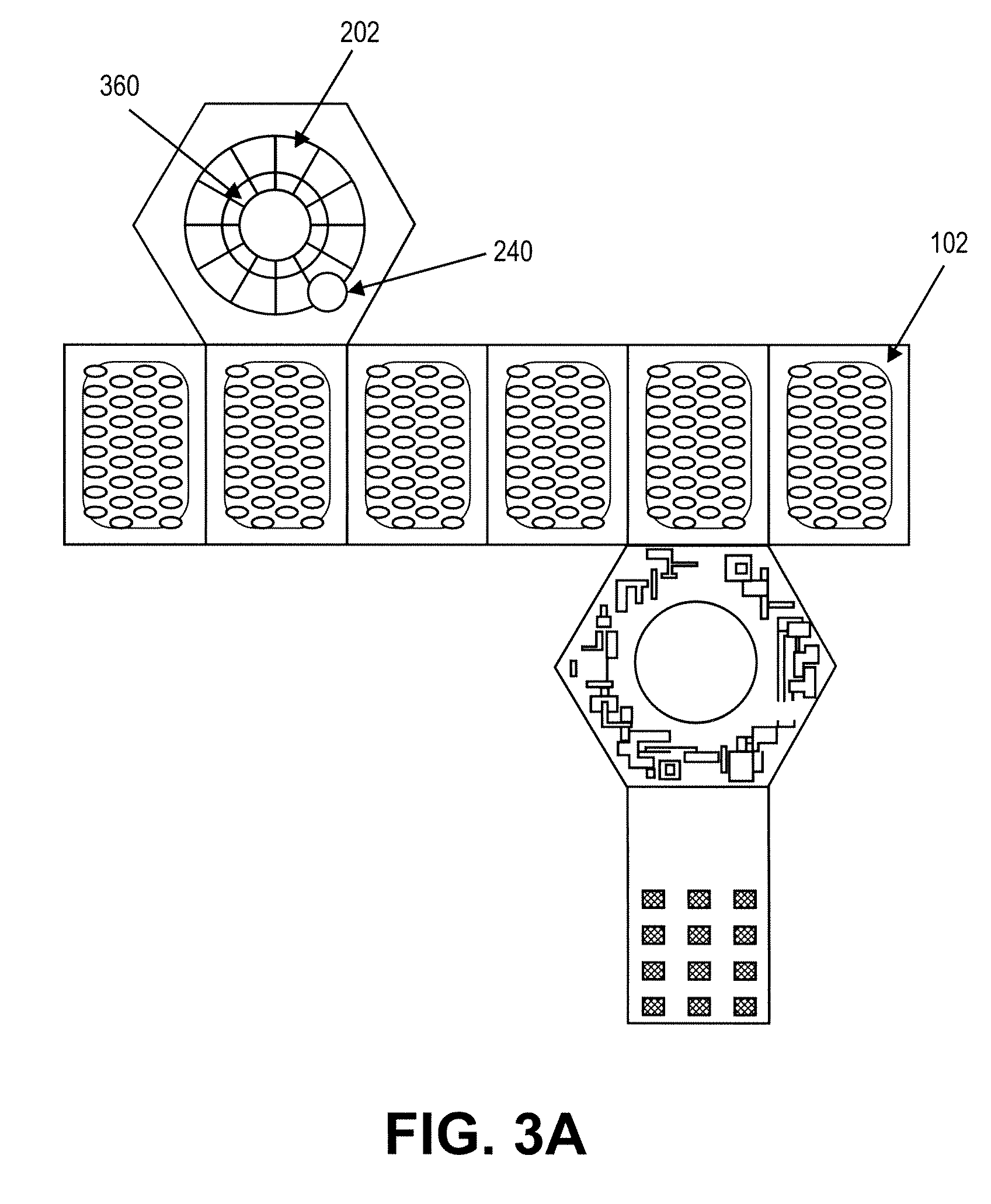
[0036]An exemplary embodiment of a photoacoustic imager 100 is shown in FIGS. 1A and 1B. According to various aspects of the disclosure, the photoacoustic imager 100 may comprise a single chip photoacoustic imager. The photoacoustic imager may include an array 102 of ultrasonic transducers 104, such as, for example, capacitive micromachined ultrasonic transducers (CMUTs) or piezoelectric ultrasound transducers, associated with a substrate 112, such as, for example, a silicon substrate. The imager 100 may include one, or an array of, optical fiber 106 configured to provide infrared illumination. For photoacoustic imaging, the power density of infrared light needed is in the order of milli-joules per square centimeter. A multi- or single-mode optical fiber is capable of delivering this power intensity.

[0037]The optical fiber 106 may be buried in a groove 108, for example, an anisotropically-etched V-groove, on a surface 110 of the silicon substrate 112. Infrared light may be guided th...


PUM

PropertyMeasurementUnit
voltageaaaaaaaaaa
core diameteraaaaaaaaaa
angleaaaaaaaaaa

Abstract

A photoacoustic medical imaging device may include a substrate, an array of ultrasonic transducers on the substrate, at least one groove etched on the substrate, at least one optical fiber, and at least one facet. Each optical fiber is disposed in one of the grooves. Each facet is etched in one of the grooves and coated with a layer of metal having high infrared reflectivity. Each optical fiber is configured to guide infrared light from a light source through the fiber and toward the respective facet. The facet is configured to reflect the infrared light toward a target.

Description

CROSS-REFERENCE TO RELATED APPLICATIONS[0001]This application claims the benefit of priority of U.S. Provisional Patent Application No. 61 / 007,023, filed on Dec. 10, 2007, and U.S. Provisional Patent Application No. 61 / 032,947, filed on Feb. 29, 2008, the disclosures of which are incorporated herein by reference in their entirety as if fully set forth herein.TECHNICAL FIELD[0002]The present disclosure relates generally to imaging devices and methods and, more particularly, to photoacoustic imaging modules and methods for medical imaging and / or diagnosis.BACKGROUND[0003]Photoacoustic Imaging (PAI) is a non-invasive medical imaging technique capable of viewing anatomical structures inside the tissue. Photoacoustic imaging may deliver both a high spatial resolution and a high contrast in medical imaging applications. To the contrary, conventional pulse-echo ultrasound medical imaging does not deliver both a high spatial resolution and a high contrast due to the similar acoustic propert...

Claims


Application Information

Patent Timeline
Patent Type & Authority Applications(United States)
IPC IPC(8): A61B6/00
CPCY10T29/49826A61B8/4472A61B5/02007A61B8/0833A61B8/12A61B8/483A61B8/4483A61B5/0086A61B5/0095A61B2562/028
Inventor CHEN, JINGKUANG
Owner STC UNM
Why Eureka
Try Eureka