Flat plate encapsulation assembly for electronic devices
- Summary
- Abstract
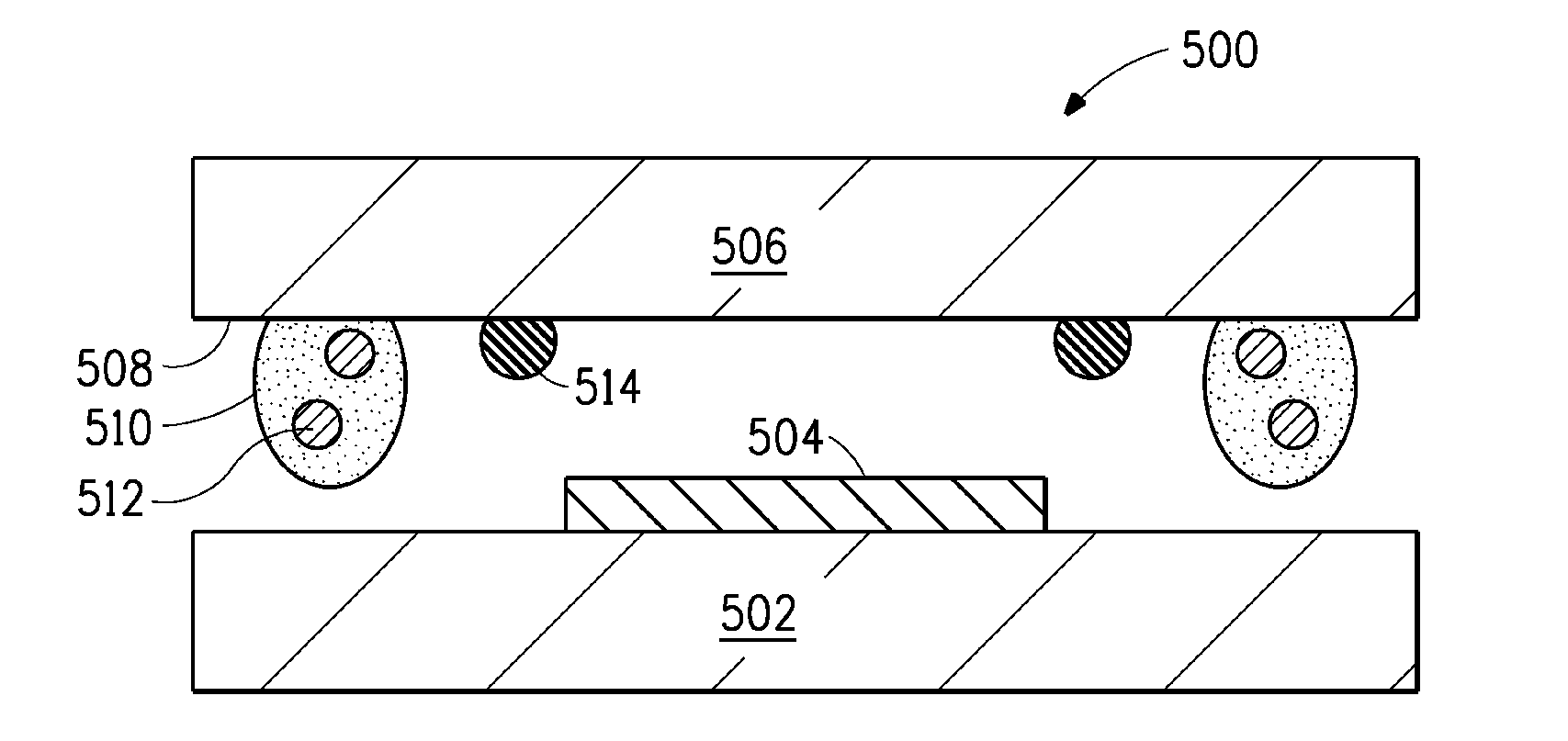
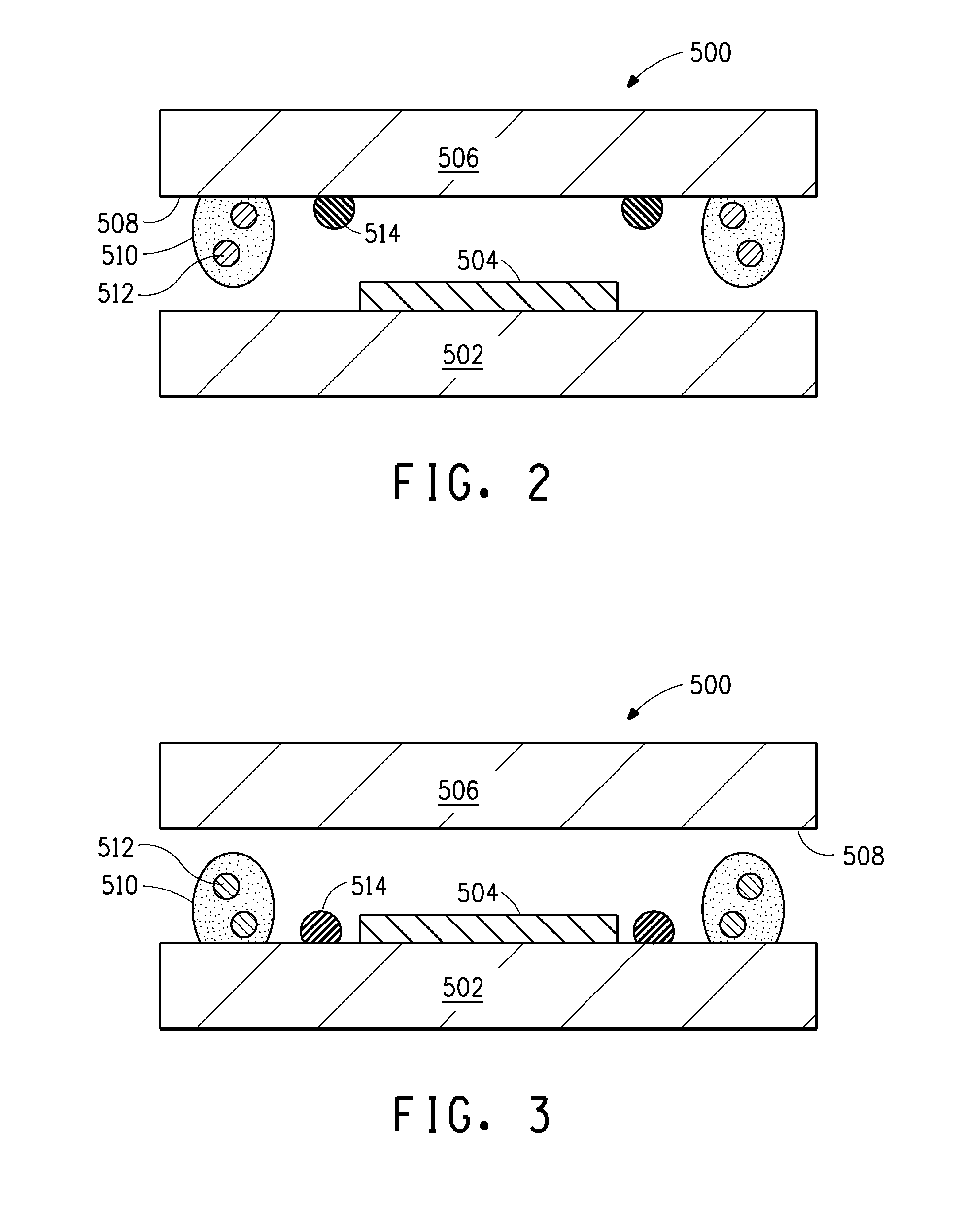
- Description
- Claims
- Application Information
AI Technical Summary
Benefits of technology
Problems solved by technology
Method used
Image

Examples
examples
[0085]FIG. 4 notes display samples made with various amounts of getter material within the encapsulation assembly. The pixel emitting area (1.000=100%) after storage testing at 60 degrees C. and 90 percent relative humidity is indicated by the lines within each test group. The test indicating full getter area shows a near 100% pixel emitting area after completion of the storage test. These tests indicated a 35 micron thick getter, occupying the entire active area of an OLED display, will achieve 1000 hours of 60×90 storage testing with little to no pixel loss.
[0086]Note that not all of the activities described above in the general description or the examples are required, that a portion of a specific activity may not be required, and that one or more further activities may be performed in addition to those described. Still further, the order in which activities are listed are not necessarily the order in which they are performed.
[0087]In the foregoing specification, the concepts hav...
PUM
 Abstract
Description
Claims
Application Information
 - Generate Ideas
- Intellectual Property
- Life Sciences
- Materials
- Tech Scout
- Unparalleled Data Quality
- Higher Quality Content
- 60% Fewer Hallucinations
Browse by: Latest US Patents, China's latest patents, Technical Efficacy Thesaurus, Application Domain, Technology Topic, Popular Technical Reports.
© 2025 PatSnap. All rights reserved.Legal|Privacy policy|Modern Slavery Act Transparency Statement|Sitemap|About US| Contact US: help@patsnap.com