Laser light source

a laser light source and laser technology, applied in the direction of laser details, laser arrangements, electrical equipment, etc., can solve the problems of difficult to achieve stable operation and failure of laser light sources, and achieve the effect of effectively preventing the generation of optical surges

Inactive Publication Date: 2010-10-28
MEGAOPTO
View PDF11 Cites 14 Cited by
  • Summary
  • Abstract
  • Description
  • Claims
  • Application Information

AI Technical Summary

Benefits of technology

[0011]In the laser light source according to the present invention as described above, for example when an optical fiber amplifier is adopted as the optical amplifier, the light from the second light source is outputted to an optical amplification fiber while the first light source is in the OFF state in which the output of pulsed light from the first light source is suspended during the duration of not less than the fixed cycle. In this case, the population inversion is suppressed in the optical amplification included in the optical amplifier, and therefore the generation of the optical surge is effectively prevented when the first light source i

Problems solved by technology

For example, the generation of the optical surge can cause a failure in the laser light source.
It is also conceivable to adopt a method of terminating the operation of the optical fiber ampli

Method used


Image

  • Laser light source
  • Laser light source
  • Laser light source

Examples


first embodiment

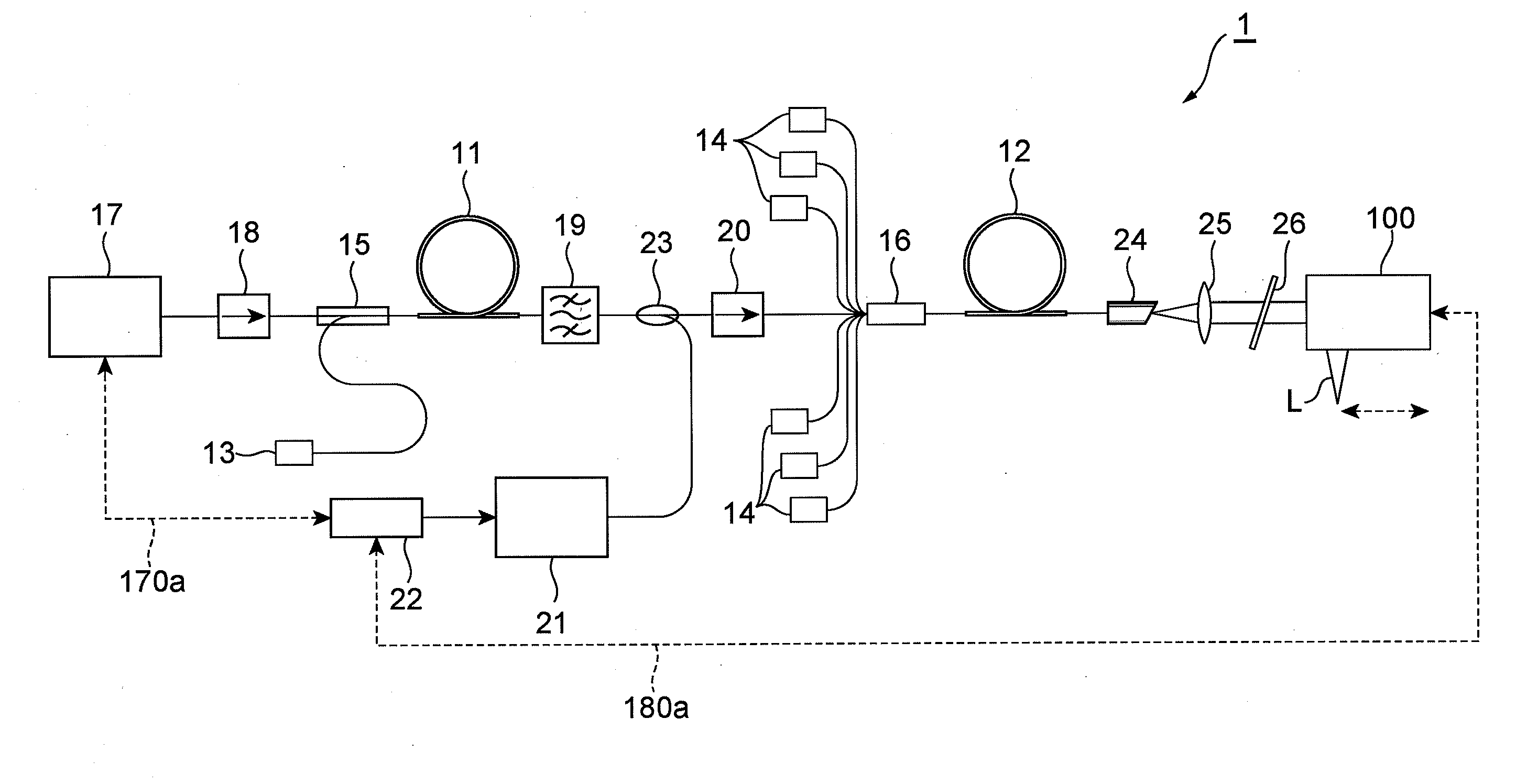
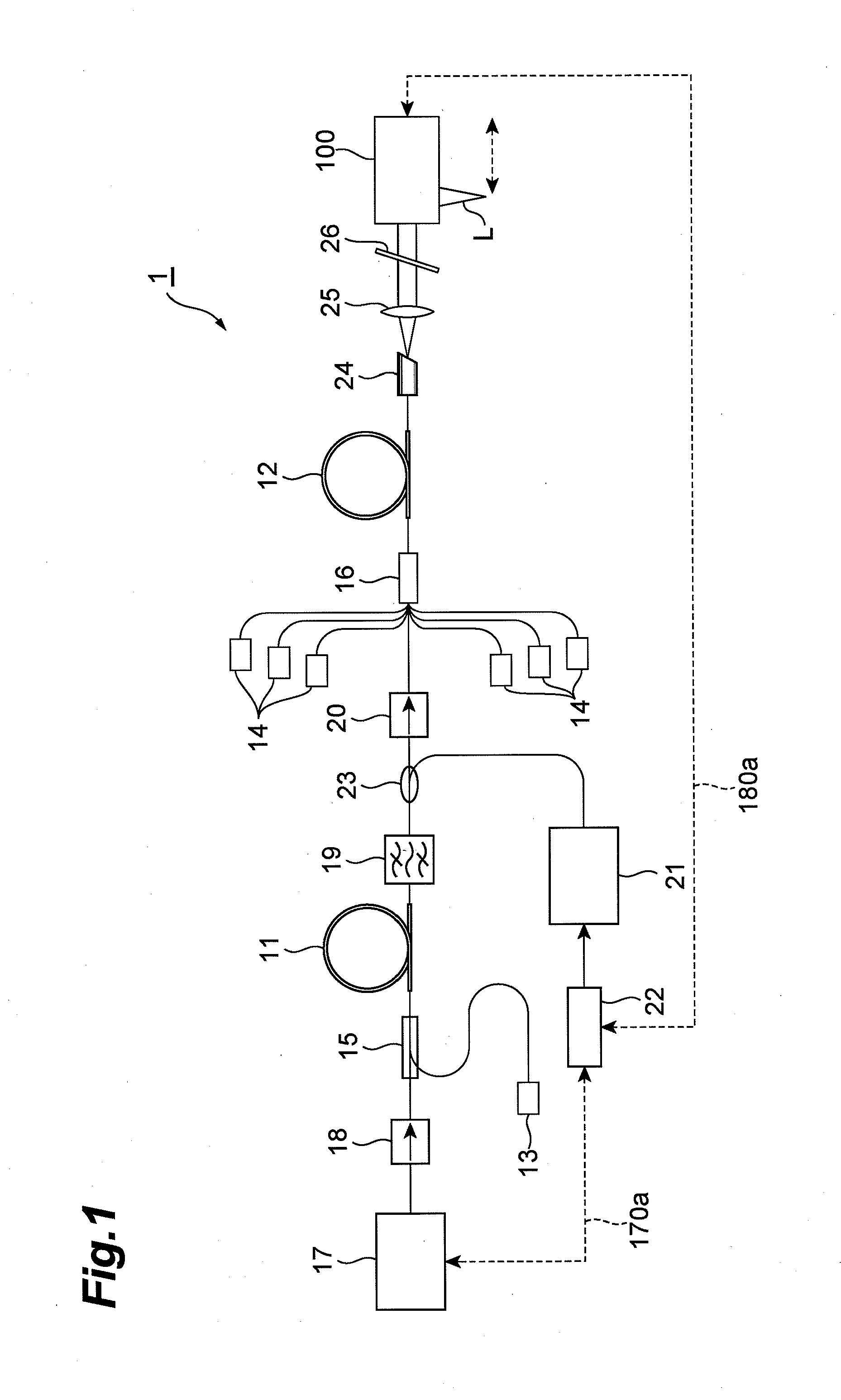
[0024]The first embodiment of the laser light source according to the present invention will be described. FIG. 1 is a view showing a configuration of the laser light source 1 according to the first embodiment. As shown in FIG. 1, the laser light source 1 comprises optical amplification fibers 11, 12, pump light sources 13, 14, combiners 15, 16, a first light source 17, optical isolators 18, 20, a band-pass filter 19, a second light source 21, a control unit 22, a WDM (Wavelength Division Multiplexing) coupler 23, an end cap 24, a lens 25, and an LWPF (Long Wavelength Pass Filter) 26.

[0025]In the laser light source 1, when pump light beams outputted from the pump light sources 13, 14 are inputted into the optical amplification fibers 11, 12, each of the optical amplification fibers 11, 12 turns into a pumped state. This results in amplifying seed light outputted from the first light source 17 of a seed light source in the light-amplifying fibers 11, 12, and the amplified light is ou...

second embodiment

[0047]The second embodiment of the laser light source according to the present invention will be described below. FIG. 8 is a view showing a configuration of the laser light source 2 according to the second embodiment. The laser light source 2 is different in the following points from the laser light source 1. Namely, the differences are that the laser light source 2 has a third light source 30 to output pulsed light with a wavelength different from those of the first light source 17 and the second light source 21, as seed light, and that the pulsed light beam outputted from the first light source 17 and the pulsed light beam outputted from the third light source 30 are multiplexed by a multiplexer 31 and then the multiplexed beams are inputted into the optical isolator 18 and inputted through the combiner 15 into the optical amplification fiber 11. The wavelength of the second light source is desirably different from a wavelength band in which the respective wavelengths of the firs...


PUM


Abstract

The present invention relates to a laser light source having a structure for effectively suppressing generation of an optical surge upon a restart after suspension of output of pulsed light. The laser light source comprises a first light source outputting light with a first wavelength as pulsed light, a second light source outputting light with a second wavelength different from the first wavelength, an optical amplification fiber as an optical amplifier amplifying the pulsed light outputted from the first light source and the light outputted from the second light source, and a control unit controlling the output of the light from the second light source in accordance with the light output from the first light source. The first light source has an ON state in which repetitive output of the pulsed light on a fixed cycle starts and continues, and an OFF state in which the output of the pulsed light is suspended during a duration of not less than the fixed cycle. The control unit controls the second light source to output the light to the optical amplification fiber during the duration of the first light source being in the OFF state, so as to suppress a rise of population inversion of a rare earth element added in the optical amplification fiber.

Description

BACKGROUND OF THE INVENTION[0001]1. Field of the Invention[0002]The present invention relates to a high-output laser light source which outputs pulsed light amplified by using an optical amplifier, and is applied to processing use, medical use, and so on.[0003]2. Related Background Art[0004]In many fields of laser processing, medical treatment, measurement or the like, there are demands for pulsed laser light having a short pulse width and a high pulse peak power and allowing for a fast repetition rate. In the laser processing field, the pulsed laser light is often implemented by Q-switching. In a Q-switched pulsed laser light source, however, there is a limit in shorter pulse generation and it is also difficult to achieve fast repetition rates because the pulse width is equivalent to a duration of time in which light travels back and forth multiple times in an optical resonator. For this reason, attention is being drawn to laser light sources using a MOPA (Master Oscillator Power A...

Claims


Application Information

Patent Timeline
IPC IPC(8): H01S3/10
CPCH01S3/06758H01S3/2308H01S3/23H01S3/1305
Inventor KAKUI, MOTOKI
Owner MEGAOPTO
Why Eureka
Try Eureka