Gas conditioning system

a technology of gas conditioning system and gas conditioning system, which is applied in the direction of combustible gas purification, combustible gas purification/modification, lighting and heating apparatus, etc., can solve the problem of insufficient attention of prior systems and processes, less desirable disposal of waste materials by incineration, and almost impossible to know the exact concentration of heavy metals in the gasification process

Inactive Publication Date: 2010-11-04
PLASCO ENERGY GROUP INC
View PDF37 Cites 118 Cited by
  • Summary
  • Abstract
  • Description
  • Claims
  • Application Information

AI Technical Summary

Benefits of technology

[0029]An object of the present invention is to provide a gas conditioning system. In accordance with an aspect of the present invention, there is provided a gas conditioning system for conditioning an input gas from one or more locations within a gasification system to provide a conditioned gas, said gas conditioning system comprising: (a) a first gas conditioner comprising one or more particle removal units for removing particulate matter from the input gas in a first conditioning stage to provide a conditioned gas and removed particulate matter; (b) a solid residue conditioner for receiving and processing said removed particulate matter to produce a secondary gas and solid waste; and (c) a second gas conditioner operatively associated with said solid residue conditioner, said second gas conditioner comprising a gas cooler and one or more further particle removal units for removing particulate matter from said secondary gas to provide a partially conditioned secondary gas, said second gas conditioner configured to pass said secondary gas through said gas cooler for cooling prior to entry of the secondary gas into the one or more further particle removal units and to pass said partially conditioned secondary gas to the first gas conditioner for further processing.

Problems solved by technology

It is becoming less desirable to dispose of waste material by incineration because of the extreme waste of fuel in the heating process and the further waste of disposing, as a residual waste, material that can be converted into a useful syngas and solid material.
The gas produced during the gasification of carbonaceous feedstock is usually very hot but may contain small amounts of unwanted compounds and requires further treatment to convert it into a useable product.
Prior systems and processes have not adequately addressed the problems that must be dealt with on a continuously changing basis.
Since each load of MSW is different from the previous one, it is almost impossible to know the exact heavy metal concentration in the gasification process.

Method used


Image

  • Gas conditioning system
  • Gas conditioning system
  • Gas conditioning system

Examples


example 1

A GCS for Production of Conditioned Gas Suitable for Use in Gas Engines

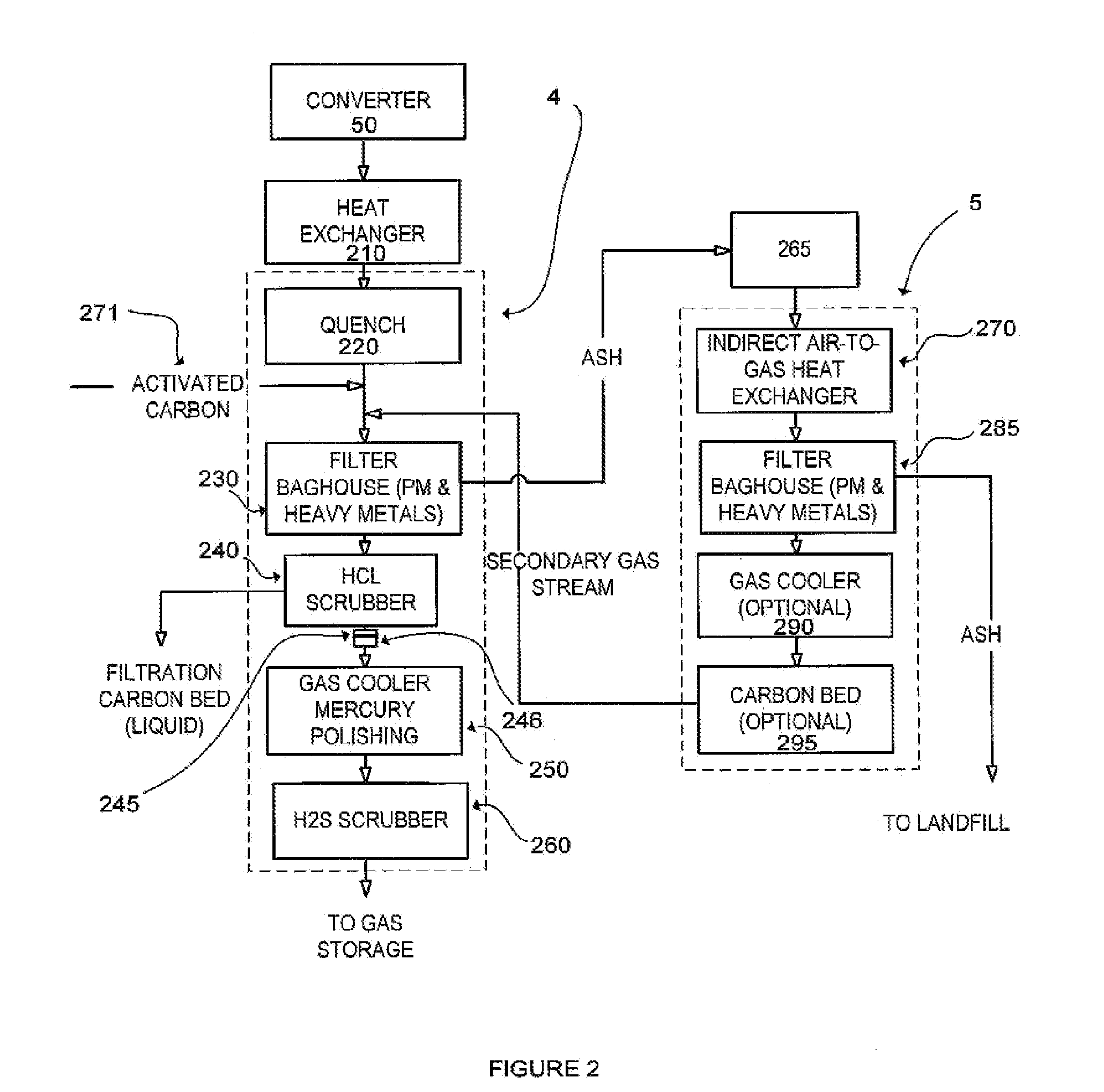
[0255]The following example describes a GCS that is configured to produce conditioned gas suitable for use in gas engines. The GCS comprises the following process operations:

Stage One Processes:

[0256]1. Evaporative Cooling (Quench)[0257]2. Dry injection system[0258]3. Particulate matter / heavy metal removal[0259]4. Processing of the solid residue in a solid residue gas conditioner and associated solid residue GC

Stage Two Processes:

[0260]5. HCl Scrubber[0261]6. Process Gas Blower[0262]7. Gas Cooler[0263]8. Mercury polisher[0264]9. Sulphur Removal

[0265]The conditioned gas produced by the above process operations is stored and subsequently heated prior to use.

[0266]The above process operations are shown in FIG. 2 and described below. As can be seen from FIG. 2 the GCS employs converging process steps and comprises a converter gas conditioner 4 integrated with a solid residue gas conditioner 5, as well as a solid resi...

example 2

Overview of a GCS Comprising Converging Process Steps

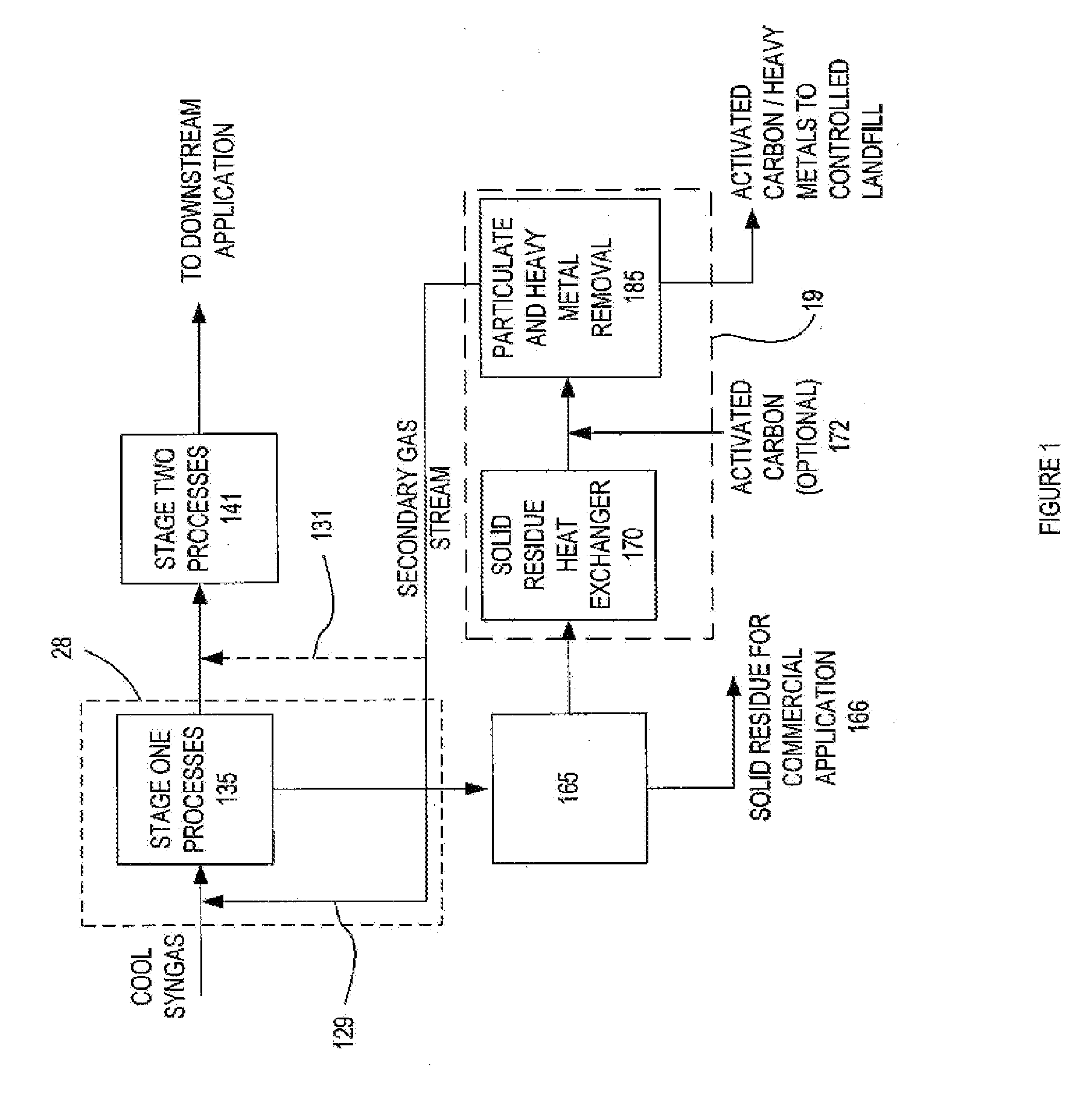
[0297]The following example provides an overview of a GCS which comprises converging process steps as shown in FIG. 9. In this example, the GCS comprises a converter gas conditioner 2 and a solid residue gas conditioner 3. in which a secondary gas stream generated in a solid residue conditioner 165 is processed in a solid residue gas conditioner 3 and then fed into the converter gas conditioner 2. In this example, the input gas has already been cooled prior to entering the GCS, for example, in a recuperator.

Stage One Processes

[0298]Activated carbon 171 is injected into the input syngas stream, and particulate matter and heavy metals are removed from the input gas using particle removal unit 130. The particulate matter and heavy metal removed from the input gas is collected and transferred to the solid residue conditioner 165 where it is converted to a solid residue and a secondary gas stream.

[0299]The secondary gas stream then ent...

example 3

Overview of a GCS for High Temperature Gas Conditioning

[0303]This example describes a GCS for high temperature gas conditioning and provides an example of a linear process sequence. An overview of the processing steps carried out by this GCS is shown in FIG. 3. At large capacity applications, in order to improve the overall thermal efficiency, the syngas can be cleaned at temperatures as high as 760° C. The syngas exiting the converter 51 is cooled to approximately 760° C. in a heat exchanger 310. This cooled syngas (input syngas) then enters the GCS 6. Particulate matter and heavy metals are then removed from the input syngas in a cyclone separator or filter 330 (Stage One Process). The following Stage Two Processes are then carried out. A chloride guard bed 340 (Nahcolite) is used to remove HCl, followed by H2S removal 360 by sorbents. Finally, a ceramic filter 362 is used to remove any particles in the hot input syngas, prior to storage of the conditioned syngas.

[0304]The GCS acc...


PUM

PropertyMeasurementUnit
temperatureaaaaaaaaaa
pressuresaaaaaaaaaa
temperatureaaaaaaaaaa

Abstract

The present invention provides a gas conditioning system for processing an input gas from a low temperature gasification system to an output gas of desired characteristics. The system comprises a two-stage process, the first stage separating heavy metals and particulate matter in a dry phase, and the second stage including further processing steps of removing acid gases, and / or other contaminants. Optional processes include adjusting the humidity and temperature of the input gas as it passes through the gas conditioning system. The presence and sequence of processing steps is determined by the composition of the input gas, the desired composition of output gas for downstream applications, and by efficiency and waste minimization.

Description

CROSS-REFERENCE TO RELATED APPLICATIONS[0001]This application claims benefit of priority under 35 U.S.C. §120 from the currently pending U.S. Non-Provisional application Ser. No. 11 / 745,441 (the “'441” application”), filed May 7, 2007. The '441 application, in turn, claims benefit of priority under 35 U.S.C. §119(e) from U.S. Provisional Application Ser. No. 60 / 746,616, filed May 5, 2006. The '441 application also claims benefit of priority to International Patent Application No. PCT / CA2006 / 000881, filed Jun. 5, 2006. The '441 application also claims benefit of priority under 35 U.S.C. §119(e) from U.S. Provisional Application Ser. No. 60 / 864,116, filed Nov. 2, 2006. The '441 application also claims benefit of priority under 35 U.S.C. §119(e) from U.S. Provisional Application Ser. No. 60 / 911,179, filed Apr. 11, 2007. The '441 application also claims benefit of priority under 35 U.S.C. §119(e) from U.S. Provisional Application Ser. No. 60 / 797,973, filed May 5, 2006. The contents of a...

Claims


Application Information

Patent Timeline
Patent Type & Authority Applications(United States)
IPC IPC(8): B01D50/00B01D46/02B01D53/14B01D53/02B01D46/42C10J1/207
CPCC10J3/20Y02E20/18C10J3/723C10J3/82C10J3/84C10J2200/09C10J2300/0946C10J2300/1223C10J2300/1238C10J2300/1634C10J2300/1671C10J2300/1681F23G5/027F23G5/085F23G2204/201F23G2209/262F23J7/00F23J2219/70Y02E50/32Y02E20/12C10J3/482C10J3/00C10K1/024C10K1/102C10J2300/1618C10J2300/165C10J2300/1693C10J2300/1884C10K1/00C10K1/002C10K1/003C10K1/004C10K1/007C10K1/02C10K1/101C10K1/12C10K1/122C10K1/143C10K1/20C10K1/26C10K1/32C10J3/463C10K1/14C10K1/16C10J2300/0983C10K3/008Y02P20/129B01D53/14B01D53/00Y02E50/30
Inventor TSANGARIS, ANDREASSWAIN, MARGARET
Owner PLASCO ENERGY GROUP INC
Why Eureka
Try Eureka