Compact, high-effectiveness, gas-to-gas compound recuperator with liquid intermediary

a gas-to-gas compound and liquid intermediary technology, applied in the field of heat exchangers, can solve the problems of limited success of alternative approaches, unachievable objectives, and most of them not aimed at high thermal efficiency, and achieve the effect of effective counterflow exchang

a gas-to-gas compound and liquid intermediary technology, applied in the field of heat exchangers, can solve the problems of limited success of alternative approaches, unachievable objectives, and most of them not aimed at high thermal efficiency, and achieve the effect of effective counterflow exchang

US20100276119A1Inactive Publication Date: 2010-11-04DOTY SCI

Image

  • Compact, high-effectiveness, gas-to-gas compound recuperator with liquid intermediary
  • Compact, high-effectiveness, gas-to-gas compound recuperator with liquid intermediary
  • Compact, high-effectiveness, gas-to-gas compound recuperator with liquid intermediary

Examples


Embodiment Construction

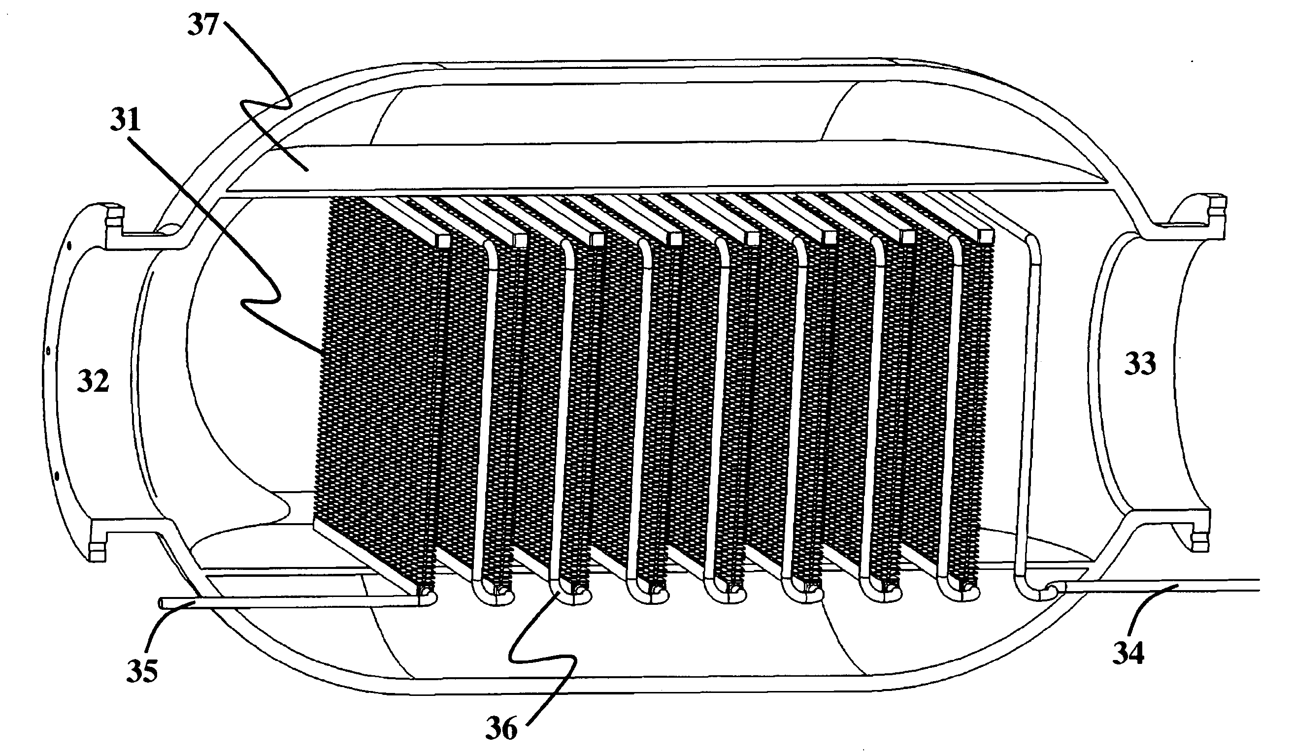
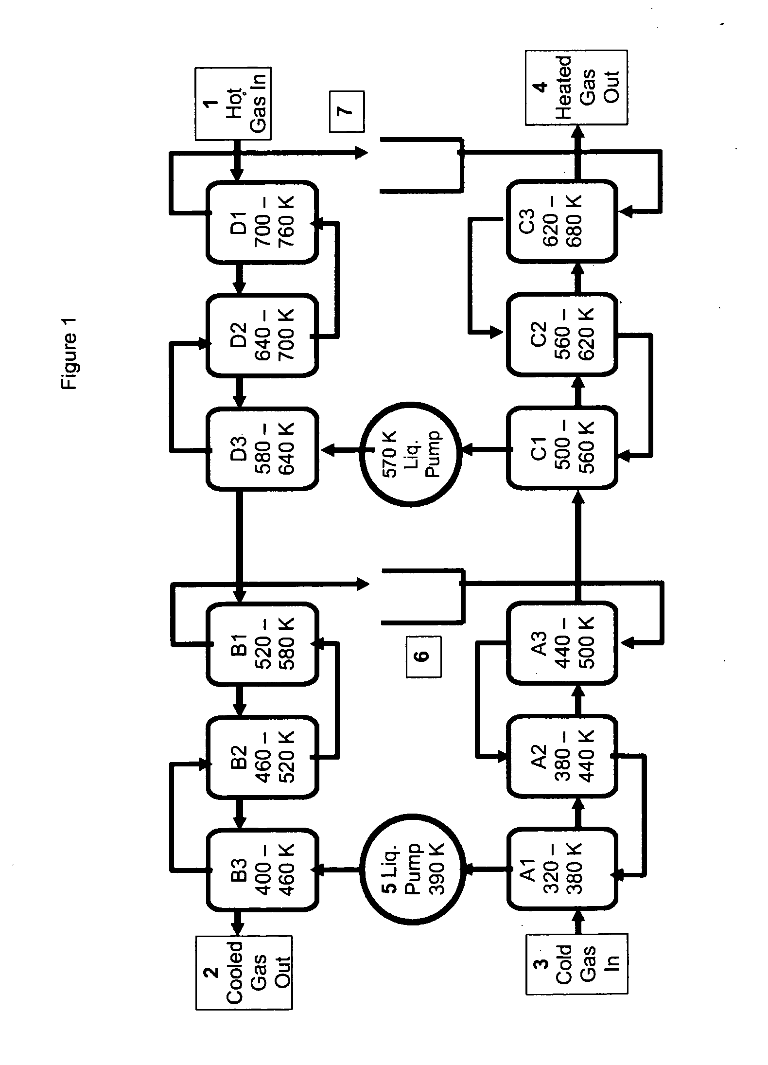
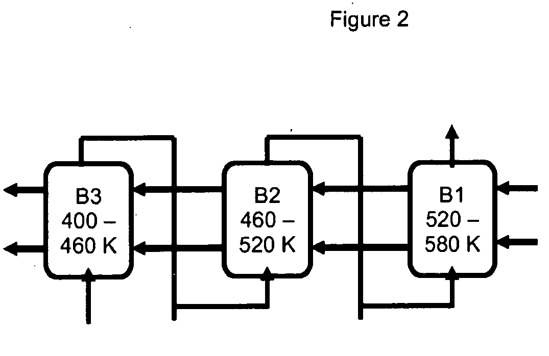
[0049]FIG. 1 illustrates a 4×3 array of 12 liquid-gas cross-flow exchanger cores with 2 liquid pumps and two different heat transfer liquids as an example of a method of achieving high-c recuperation between two isolated fluids of low thermal conductivity, gas-1 and gas-2, identified in the figure using hollow lines. These fluids have mean thermal conductivity less than 0.4 W / m-K (that of H2 at ˜720 K) and will usually be gases with kt less than 0.06 W / m-K. Thus, for improved clarity, they are generally referred to as gases herein, though applications where these fluid streams would be viscous organic liquids are seen in a co-pending patent application. Both gas-1 and gas-2 are shell-side, sometimes also called “fin-side”. In this example, gas-1 is the hot source stream, and gas-2 is the cold stream being heated to nearly the entry temperature of gas-1. Often, the hotter gas will be at lower pressure than the cooler gas, but the reverse relationship is also possible.

[0050]In the exa...


PUM


Abstract

A liquid-loop compound recuperator is disclosed for high-ε heat exchange between a first shell-side fluid stream and a second shell-side fluid stream of similar thermal capacity rates (W / K). The compound recuperator is comprised of at least two fluid-to-liquid (FL) recuperator modules for transfer of heat from a shell-side fluid, usually a gas, to an intermediary tube-side heat transfer liquid (HTL). Each FL module includes a plurality of thermally isolated, serially connected, adjacent exchanger cores inside a pressure vessel. The cores are rows of finned tubes for cross-flow transfer of heat, and they are arranged in series to effectively achieve counterflow exchange between the HTL and the shell-side stream. The HTL may be water, an organic liquid, a molten alloy, or a molten salt.

Description

CROSS-REFERENCE TO RELATED APPLICATIONS[0001]This application claims the benefit of U.S. application No. 61 / 016,247 filed Dec. 21, 2007, and the benefit of U.S. application No. 61 / 034,148 filed Mar. 5, 2008, each of which is incorporated herein by reference for all purposes.FIELD OF THE INVENTION[0002]The field of this invention is heat exchangers, and more particularly, compact, gas-to-gas recuperation at high effectiveness for clean gases of similar heat capacity rates using compound recuperators with liquid intermediary.BACKGROUND OF THE INVENTION[0003]Gas-to-gas recuperation with both high thermal effectiveness and order-of-magnitude improvement in cost effectiveness is critical to addressing global energy needs, as shown in at least two co-pending patent applications. From a manufacturing perspective, the challenges arise from the fact that it is not practical to produce heat exchangers with closely-spaced fins on both the inside and outside of tubes, and alternative approaches...

Claims


Application Information

Patent Timeline
04 Nov 2010
Publication
US20100276119A1
IPC
F28D15/00; F28D1/04; F28F1/28
CPC
F28D1/0477; F28D1/05316; F28D15/00; F28D7/163; F28D7/08
Inventors
DOTY, F. DAVID