Node and a Method for use in a Wireless Communications System

Active Publication Date: 2010-11-04
TELEFON AB LM ERICSSON (PUBL)
4 Cites 79 Cited by

AI-Extracted Technical Summary

Problems solved by technology

On the other hand, an on-frequency repeater is prone to self-interference since the same signal is received and transmitted at virtually the same time.
Therefore, the gain that can be applied in such a repeater is limited to a level that will not cause excessive self-interference.
Even with such measures to reduce self-interference, th...

Benefits of technology

[0011]It is an object of the invention to provide a relay and/or ...

Abstract

The invention relates to a relay or repeater node (21) for use in a wireless communications system said node comprising a receive antenna (23) for receiving a signal through a wireless connection, an amplifier (30) for amplifying the signal and a transmit antenna (27) for forwarding the amplified signal, said node further comprising a mode switching unit (31) for switching between at least a first and a second mode of operation of the node in dependence of an amplification gain requirement. This enables optimization of the node for varying conditions in the network.

Application Domain

Repeater circuitsRadio relay systems +1

Technology Topic

Image

  • Node and a Method for use in a Wireless Communications System
  • Node and a Method for use in a Wireless Communications System
  • Node and a Method for use in a Wireless Communications System

Examples

  • Experimental program(1)

Example

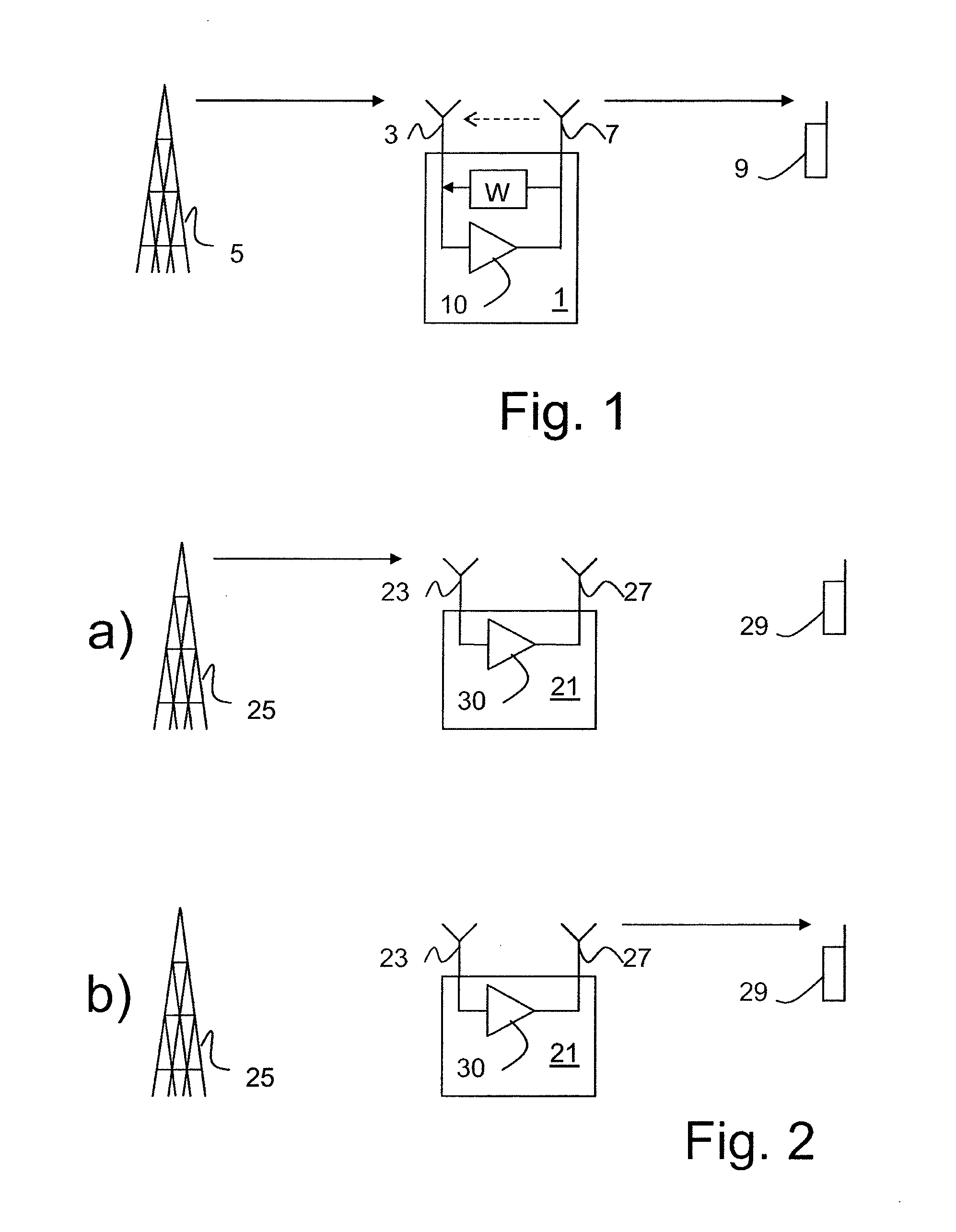
[0034]FIG. 1 illustrates an on-frequency repeater function, that is, the repeater receives and transmits on the same resource at substantially the same time, hence causing self interference from the output to the input, although in practice there will always be a small delay. The repeater 1 comprises a receive antenna 3 arranged to receive a signal from a base station 5 and a transmit antenna 7 arranged to forward the signal to a mobile terminal 9. An amplifier 10 provides a gain between the receive antenna 3 and the transmit antenna 7. The signal is forwarded on the same resource on which it was received. This means that the repeater 1 uses the same frequency, non-orthogonal coding etc. and forwards the signal immediately upon receiving it.
[0035]Such repeaters are prone to self-interference, and are therefore typically designed so that the transmit and receive antennas are isolated from each other to the extent possible. As discussed above self-interference cancellation methods based on feedback signals between the transmit antenna and the receive antenna are used to reduce self-interference. In FIG. 1 this feedback signal is illustrated by a unit W indicating that it applies a (complex valued) weighting of the feedback signal. Still, if the signal power feed back to the input becomes too high, self-interference cannot be completely ruled out in such repeaters. Self-interference is illustrated in FIG. 1 by a dashed line from the transmit antenna to the receive antenna.
[0036]FIG. 2 illustrates a repeater 21 arranged to forward the received signal on a different resource from the one on which it was received. Preferably, the resources are substantially orthogonal, to minimize the interference between them. For example, the repeater 21 may be a frequency translating repeater. Again the repeater 21 comprises a receive antenna 23 arranged to receive a signal from a base station 25 and a transmit antenna 27 arranged to forward the signal to a mobile terminal 29. To illustrate the use of different resources, the receiving function and the transmission function are shown in two different parts of the figure, a) and b), respectively.
[0037]FIGS. 3a-3c illustrate different ways to utilize different resources. In each of these figures the horizontal axis represents time t. In FIG. 3a, the receive function Rx and the transmit function Tx are assigned different time intervals, so that the repeater 11 never transmits and receives at the same time. In FIG. 3b the receive function Rx and the transmit function Tx are assigned different frequency domains, f1 and f2, respectively. In FIG. 3c the receive function Rx and the transmit function Tx are assigned different orthogonal spreading codes, code1 and code2, respectively.
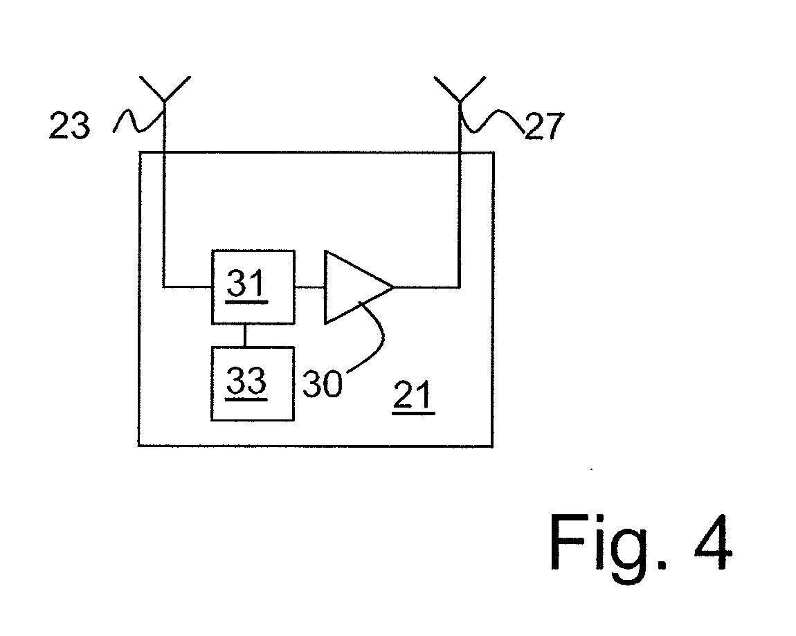
[0038]FIG. 4 illustrates a repeater 21 according to an embodiment of the invention, which is able to switch between a first and a second mode of operation depending on the conditions. As before, the repeater 21 comprises a receive antenna side having at least one receive antenna 23 arranged to receive a signal from a base station 25 and a transmit antenna side having at least one transmit antenna 27 arranged to forward the signal to a mobile terminal 29. An amplifier 30 provides a gain between the receive antenna 23 and the transmit antenna 27. The repeater 21 also comprises a mode switch 31 arranged between the receive antenna 23 and the transmit antenna 27 in series with the amplifier 30. The mode switch is arranged to switch between a first and a second mode of operation of the repeater 21. Which mode to switch to may be determined by a mode selector 33 arranged in the repeater 21. Alternatively, it may be determined in the sender or the receiving node, or possibly in a distributed fashion over those nodes. In the latter case, information about the selected mode can be received in the repeater node 21 by means of the receive antenna 23 and processed in the mode switch 31. The repeater 21 may also comprise other units, for example, a feedback unit, as shown in FIG. 1 for interference cancellation.
[0039]In the first mode the relay or repeater will transmit concurrently while receiving on the same frequency. This is suitable in situations where the SIR is good, which will often be the case, for example, when the path loss is low. In the second mode, the relay/repeater node will use different resources for receiving and transmitting. The resources are preferably orthogonal, to minimize interference between them. As discussed in connection with FIGS. 3a-3c, the resources may be divided in time, in frequency and/or in the code domain.
[0040]One advantage of the time duplex operation shown in FIG. 3a is that the relay/repeater node can decode the received signal and retrieve the payload information without noise. The noise free version can then be amplified and transmitted instead of amplifying a signal comprising both the payload and the noise.
[0041]In a preferred embodiment, the condition for selecting the first or the second mode is whether the required relay/repeater node gain is above or below a gain threshold value G0. The gain threshold value will inherently be determined by the relay/repeater node design, i.e. the isolation between the transmit and receive antennas, whether any interference cancellation is applied, etc. First, the gain needed in the relay/repeater node can be determined as
GRN=PRN(TX)/PRN(RX)=PMN(RX)GRN→MN/PRN(RX).   (1)
where
[0042]TX and RX stand for transmit and receive respectively,
[0043]RN denotes for relay/repeater node,
[0044]MN denotes the mobile node (or rather the receiving node), and
[0045]P indicates power and
[0046]G indicates gain.
[0047]The repeater amplification gain is based on at least the repeater to the receiver(s) channel gain, where the considered receiver or receivers may change over times, and when a group of receivers are targeted, the channel gain to the receiver with the 0 worst performance is considered.
[0048]As can be seen from Eq. 1, assuming that the desired MN receive-power PMN(RX) is known, and the relay/repeater node receive-power PRN(RX) is given, the required relay node gain depends (mainly) on the relay/repeater node to mobile node channel gain GRN→MN. The desired MN receive-power PMN(RX) and the relay/repeater node receive-power PRN(RX) are both given by the quality of service requirements, bit error rate, data rate, and noise plus interference situation.
[0049]The relay node gain GRN should be compared to the threshold. The switching between the modes in this embodiment can be described through
if GRN 0, then Mode 1
else if GRN≧G0, then Mode 2   (2)
[0050]As mentioned above, in the preferred embodiment the second mode can utilize different resources in terms of time, frequency or coding. In an alternative embodiment, both the first and the second mode involve using different resources for transmitting and receiving. In this case, the first mode may be, for example, using different codes for transmitting and receiving, while the second mode may be using different frequencies, or separating the received and transmitted signals in time.
[0051]More than one threshold may be used, to enable selection between several different modes. In this case, the first mode may still be using the same resource for transmitting and receiving and two or three additional modes may be defined in which receiving and transmitting use different resources. Alternatively all modes may use different resources. For example, the first mode may be using different orthogonal spreading codes, the second mode using different frequencies and the third mode separating the signals in time. The selection between several different modes may be performed in one step, or in several steps. In the former case, each mode is assigned to an interval of amplifier gain values and the mode matching the actual amplifier gain is selected. In the latter case, assuming a first mode is used, a switch to the second mode is performed when the amplifier gain passes a first threshold and a switch to the third mode is performed when the amplifier gain passes a second threshold.
[0052]In order to determine which mode to operate in, by calculating the gain or the relay/repeater node, at least the gain between the relay/repeater node to the receiving node must be determined. This can be done in several different ways. For example the link gain may be measured proactively and reported to the mode selector, which, as stated above may be located in the sender, the receiver or the relay/repeater node, or may be distributed between them. Alternatively, a reactive type of operation may be used.
[0053]In one possible reactive embodiment of the invention, a connection is always initially set up in the second mode, that is, in the mode where the relay/repeater receives and sends on different resources. In this starting phase, the channel and gains are measured and if suitable, the relay/repeater node is switched to operate in the first mode.
[0054]FIG. 5 is an example of a reactive embodiment of the method as discussed above.
[0055]In step S51 a default mode of operation is applied when amplifying and forwarding signals. This default mode is preferably the second mode.
[0056]In step S52 a required amplifying gain is determined.
[0057]In step S53 the required amplifying gain is compared to a predetermined threshold.
[0058]In step S54 a mode of operation is selected in dependence of the result of the comparison performed in step S53. As discussed above, the selection may be performed in the repeater node itself, in the sender or transmitter, or distributed between two or more of these units.
[0059]In step S55 the selected mode of operation is applied to the repeater node.
[0060]In a proactive embodiment the procedure may instead start with measuring the link gain and using this to determine the required amplifying gain in step S52.
[0061]As will be understood, different relaying modes may be used simultaneously in the uplink and downlink communication through the same relay or repeater node.
[0062]FIG. 6 illustrates a situation similar to that of FIG. 2, in which the base station 25 and/or the mobile terminal 29 comprise logic units 35, 37, respectively, arranged to determine the preferred mode of operation to be used by the relay node 21. As illustrated by the dashed arrows in FIG. 6, the base station 25, the mobile terminal 29, or both, may send a message, conveying information, to the repeater/relay node 21 regarding operation mode. The message may be an order that has to be followed or a recommendation that the relay/repeater node 21 based on further information housed or collated by the repeater/relay that account for when deciding which mode to operate in. In the latter case, the node 21 may base its decision on information received from either the base station 25, the mobile terminal 29, or both.
[0063]While the description above has been based on downlink communication, that is, communication from the base station 25 to the mobile terminal 29, the skilled person will readily understand that the structure and function of the inventive repeater node will be completely analogous to that described above regardless of the nature of the sending and transmitting node. That is, the teachings of this document could be applied to uplink or downlink communication, as well as to communication between any two units involving the use of a repeater and/or relay node between the units. Therefore, the scope of the claims should not be limited to communication in any particular direction, or between any particular type of communicating units.

PUM

no PUM

Description & Claims & Application Information

We can also present the details of the Description, Claims and Application information to help users get a comprehensive understanding of the technical details of the patent, such as background art, summary of invention, brief description of drawings, description of embodiments, and other original content. On the other hand, users can also determine the specific scope of protection of the technology through the list of claims; as well as understand the changes in the life cycle of the technology with the presentation of the patent timeline. Login to view more.

Similar technology patents

Superposition coding

InactiveUS20100046644A1Reduce complexityImprove performanceMultiple modulation transmitter/receiver arrangementsSecret communicationSuperposition codingEngineering
Owner:MOTOROLA MOBILITY LLC

Vertical adaptive antenna array for a discrete multitone spread spectrum communications system

InactiveUS20050002440A1Improve performanceImprove signal-to-interference levelPolarisation/directional diversityMultiplex code allocationSpatially adaptiveSelf adaptive
Owner:AT&T MOBILITY II LLC

Classification and recommendation of technical efficacy words

Why Eureka
Try Eureka