

Print dipole antenna and manufacturing method thereof
a technology of dipole antenna and manufacturing method, which is applied in the direction of antennas, antenna feed intermediates, electrical devices, etc., to achieve the effects of simple structure, low fabrication cost and high application valu
- Summary
- Abstract
- Description
- Claims
- Application Information
AI Technical Summary
Benefits of technology
Problems solved by technology
Method used
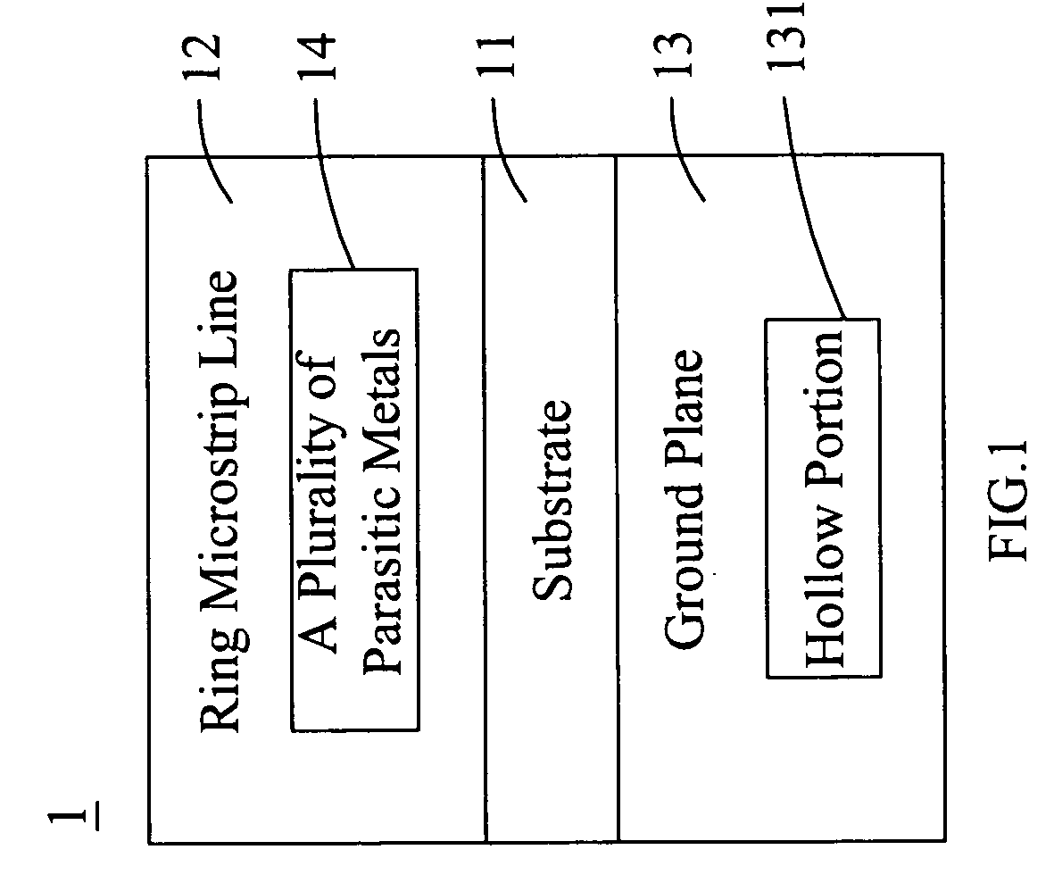
Image

Examples
first embodiment
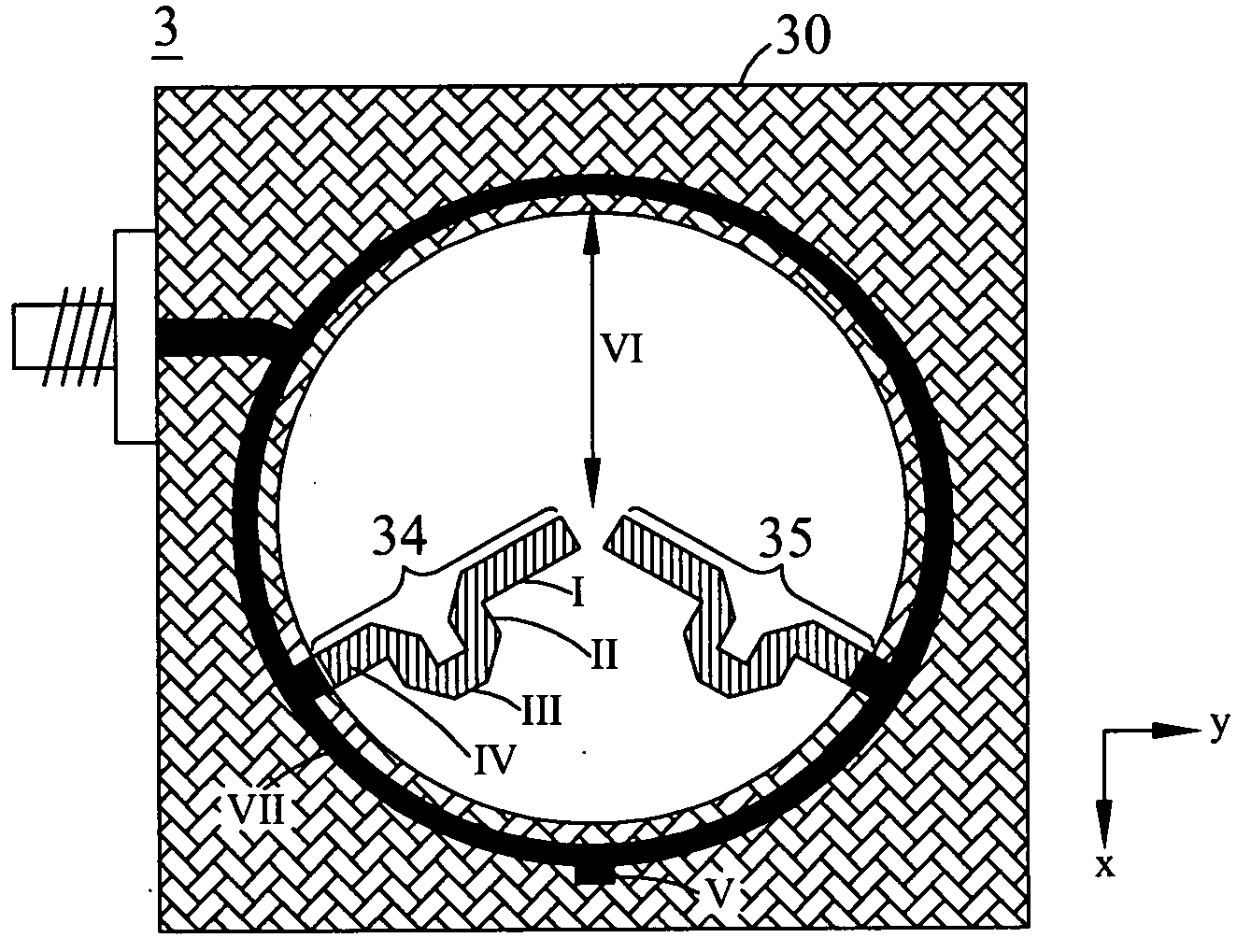
[0040]Refer subsequently to FIG. 3, wherein a drawing for the print dipole antenna according to the present invention is shown. In the Figure, the print dipole antenna 3 comprises two parts, in which the first part is the ring multiplexer / demultiplexer 30 used as a feed network, while the second part are two parasitic metals 34 and 35 used as radiation components. Herein, as shown in FIG. 3B, the ring multiplexer / demultiplexer 30 consists of a substrate 31, a ring microstrip line 32 and a ground plane 33. The ring microstrip line 32 further includes an input end port 321, two output end port 322 and 323 as well as an open circuit end 324. The two parasitic metals 34 and 35 is respectively connected to the two output end ports 322 and 323, and the two parasitic metals 34 and 35 represent the two dipole arms found in the conventional dipole antenna. Additionally, the structure of the ring multiplexer / demultiplexer 30 comprises a plate antenna built by using a double-sided print FR4 ci...
second embodiment
[0042]Refer now to FIG. 4, wherein a drawing for the print dipole antenna according to the present invention is shown. For the print dipole antenna design illustrated in FIG. 2, there exist four resonance frequencies in the 2˜6 GHz frequency band, whereas the second embodiment fixes the two times of the central frequency of the ring multiplexer / demultiplexer used as the feed network at the Wireless Local Area Networks (WLANs) 5.2 GHz, and uses the first and the fourth resonance frequencies for frequency band plan so as to construct the dual-frequency operation mode. Herein the lower frequency band is selected to be WLANs 2.4 GHz (2.4-2.484 GHz), and the higher frequency band is WLANs 5.2 GHz (5.15-5.35 GHz). Since the lower frequency resonance frequency is lower than the central frequency 2.6 GHz of the ring multiplexer / demultiplexer, the lengths of the two parasitic metals are accordingly required to be added, which may be achieved by extending the parasitic metals toward the cente...
fifth embodiment
[0047]Refer subsequently to FIG. 13, wherein a drawing for the print dipole antenna according to the present invention is shown. The fifth embodiment is intended to more effectively exploit all resonance frequencies within two times of the central frequency of the ring multiplexer / demultiplexer, and since many common communication system frequency bands exist between frequency bands 1.7 GHz to 3 GHz, if the two times of central frequency is designed to be located at WiMAX 3.5 GHz, then when operating around lower frequency central frequency, it is possible to provide such communication systems with frequency bands required for normal operations; therefore, the two times of the central frequency is chosen to be 3.5 GHz, and at the same, the integral operation frequency bands are also herein determined. The structure of the print dipole antenna in the fifth embodiment is shown as FIG. 13, whose detailed specifications comprise: the central frequency of the ring multiplexer / demultiplex...
PUM
| Property | Measurement | Unit |
|---|---|---|
| thickness | aaaaa | aaaaa |
| resonance frequencies | aaaaa | aaaaa |
| resonance frequencies | aaaaa | aaaaa |
Abstract
Description
Claims
Application Information