Assembly of a capacitive acoustic transducer of the microelectromechanical type and package thereof

a capacitive acoustic transducer and microelectromechanical technology, applied in the direction of microphone structural association, semiconductor electrostatic transducer, loudspeaker, etc., can solve the problems of acoustic transducers that operate in unfavorable working environments, affecting the proper operation of the mems sensing structure and the reading of electronics, and the design of such devices is particularly problemati

Active Publication Date: 2010-11-11
STMICROELECTRONICS SRL
View PDF12 Cites 213 Cited by
  • Summary
  • Abstract
  • Description
  • Claims
  • Application Information

AI Technical Summary

Problems solved by technology

At the design stage, it must also be considered that acoustic transducers typically operate in unfavourable working environments, for example ones subject to high levels of RF radiation (when integrated in mobile phones, or similar wireless-communication devices).
The presence of acoustic access ports, directly communicating with the external environment, designed to enable passage of the acoustic-pressure waves towards the membrane 2, leads to the further requirement of providing appropriate screens for the incident light and barriers for the particles of dust or other material, which could jeopardize proper operation of the MEMS sensing structure and of the reading electronics.
Therefore, there is a wide range of constraints imposed upon assembly of a capacitive MEMS microphone and upon the package for the resulting assembly, which render design thereof particularly problematical, in particular where very low size is required.
This assembly solution is, however, very complex, posing various problems of technological compatibility.
Also this solution is not, however, free from drawbacks, amongst which the fact of entailing large dimensions for accommodating side-by-side the two dice of the acoustic transducer and for providing the corresponding package.
Furthermore, this solution fails to offer the designer an ample freedom (as instead would be desirable) in dimensioning of the chambers of the acoustic transducer, for determination of its electrical characteristics.
A solution of this type is complex to implement in so far as it entails laborious procedures of bonding with the further supporting die and of machining of the same supporting die, and is not free from problems linked to the required dimensions, which are large both in a lateral direction and in a vertical direction.
Furthermore, the dimensions of the front and back chambers of the acoustic transducer are defined in a fixed way by the dimensions of the supporting die, and consequently pose constraints on sizing of the microphone performance.

Method used


Image

  • Assembly of a capacitive acoustic transducer of the microelectromechanical type and package thereof
  • Assembly of a capacitive acoustic transducer of the microelectromechanical type and package thereof
  • Assembly of a capacitive acoustic transducer of the microelectromechanical type and package thereof

Examples


first embodiment

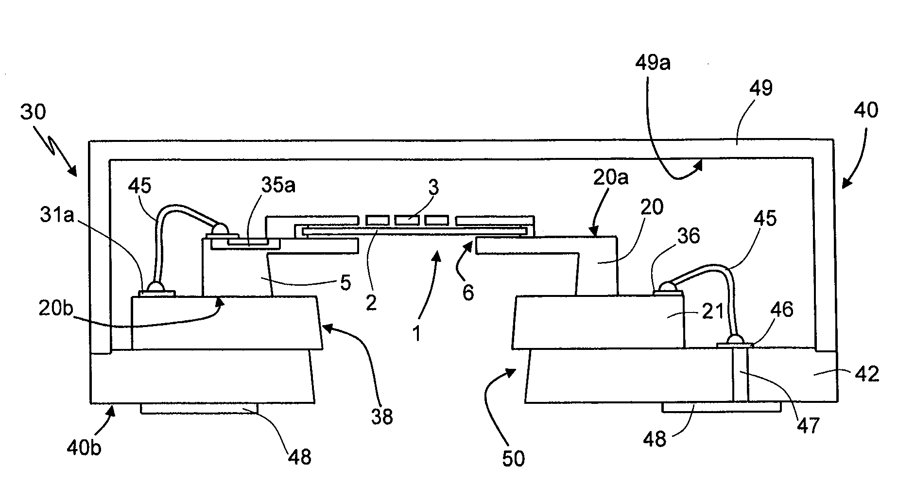
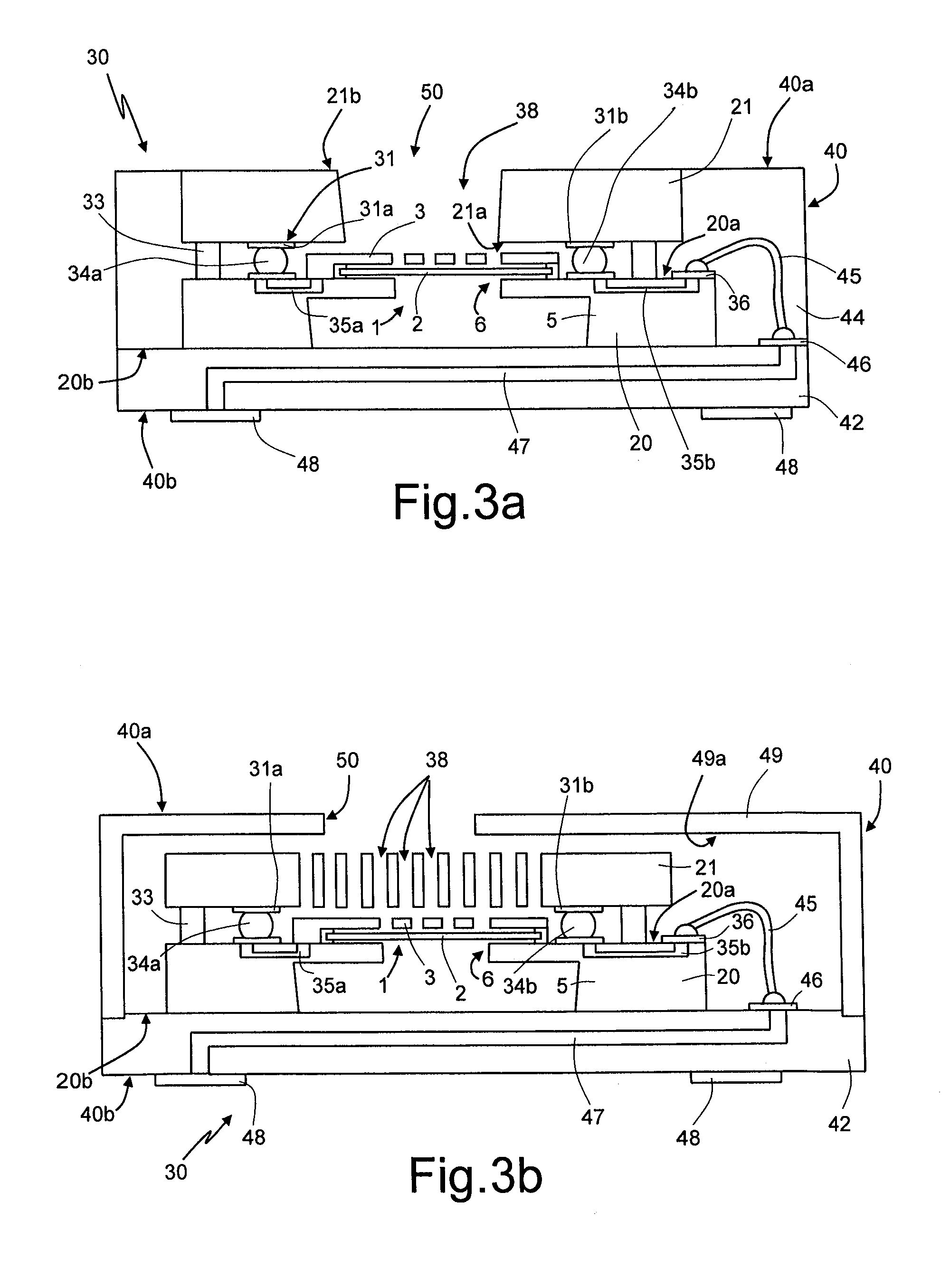
[0045]FIG. 3a shows the present disclosure, for a MEMS-capacitive-microphone assembly, designated by 30, of the top-port type, i.e., where the access port that enables entry of the acoustic-pressure waves is provided in a position corresponding to a top surface of the MEMS capacitive microphone (opposite that is, to the surface for coupling to an external printed circuit board, which carries for this purpose appropriate electrical contacts). In FIG. 3a (and in the subsequent figures) parts that are similar to others already described previously (not described again herein) are designated by the same reference numbers.

[0046]The first die 20, integrating the MEMS sensing structure 1 (illustrated schematically herein, and made, for example, as described in detail with reference to FIG. 1), is directly coupled (without, that is, interposition of further substrates or coupling dice) to the second die 21, integrating the ASIC that provides the reading electronics, to which it is electrica...

second embodiment

[0065]FIGS. 6a-6c show variants of the MEMS-capacitive-microphone assembly 30 and of the corresponding package 40, once again of the top-port type (it is emphasized that, also for this embodiment and for the subsequent ones that will be described, it may be conceived to provide, alternatively, a single through hole 38 or a plurality of through holes 38 through the entire thickness of the second die 21, even though this is not explicitly illustrated).

[0066]This second embodiment envisages further reduction of the dimensions of the package 40 and further improvement of the EMI-shielding performance, eliminating the interconnections via wire bonding between the assembly constituted by the first and second dice 20, 21 and the base substrate 42, and using, instead, for this purpose so-called “through silicon vias”51, provided (in a per-se known manner) through the entire thickness of the first die 20.

[0067]In particular, the through vias 51 connect in this case the second conductive bump...

third embodiment

[0072]FIGS. 7a-7b show variants of a third embodiment, corresponding to a MEMS capacitive microphone 30 of the bottom-port type, where, that is, the access port that enables entry of the acoustic-pressure waves is provided at a bottom surface of the MEMS capacitive microphone (in particular, the second outer face 40b, corresponding to the surface for coupling of the package 40 to an external printed circuit board). The acoustic access port 50 is in this case constituted by a through opening that traverses the base substrate 42 for an entire thickness thereof.

[0073]The first die 20 is stacked upside down (using the flip-chip technique) on the second die 21, with the necessary electrical and mechanical connections made using the bump-bonding technique. Once again, there are consequently present the first conductive bumps 34a, which electrically connect the first electrical contact pads 31a to the first buried electrical paths 35a. Also here the closing ring 33 is provided, made of met...


PUM


Abstract

A microelectromechanical-acoustic-transducer assembly has: a first die integrating a MEMS sensing structure having a membrane, which has a first surface in fluid communication with a front chamber and a second surface, opposite to the first surface, in fluid communication with a back chamber of the microelectromechanical acoustic transducer, is able to undergo deformation as a function of incident acoustic-pressure waves, and faces a rigid electrode so as to form a variable-capacitance capacitor; a second die, integrating an electronic reading circuit operatively coupled to the MEMS sensing structure and supplying an electrical output signal as a function of the capacitive variation; and a package, housing the first die and the second die and having a base substrate with external electrical contacts. The first and second dice are stacked in the package and directly connected together mechanically and electrically; the package delimits at least one of the front and back chambers.

Description

BACKGROUND[0001]1. Technical Field[0002]The present disclosure relates to assembly of an acoustic transducer, in particular a microelectromechanical (MEMS) capacitive microphone, to which the following description will make explicit reference, without this implying any loss of generality, and to a package for the assembly thus obtained.[0003]2. Description of the Related Art[0004]In a manner customary in this technical field, the term “package” will be used herein to indicate the casing or coating that surrounds, totally or partially, the die or dice of semiconductor material of the acoustic transducer, enabling electrical connection thereof from outside, for example, using the surface-mount (SMD) technique.[0005]As is known, an acoustic transducer, for example a MEMS microphone of a capacitive type, generally comprises a MEMS sensing structure, designed to transduce acoustic-pressure waves into an electrical quantity (in particular, a capacitive variation), and a reading electronic...

Claims


Application Information

Patent Timeline
Patent Type & Authority Applications(United States)
IPC IPC(8): H04R19/04
CPCB81B7/0061B81B2201/0257H04R1/04H04R1/06H04R1/086H04R2201/003H04R19/005H04R19/04B81B3/0018B81C1/00158H04R1/2838H01L2224/48479H01L2224/48091H01L2224/48137H01L2224/48145H01L2924/16151H01L2924/16152H01L2924/00014H01L2224/48471H01L2224/4554H01L2924/00012
Inventor CONTI, SEBASTIANOVIGNA, BENEDETTOCORTESE, MARIO FRANCESCO
Owner STMICROELECTRONICS SRL
Why Eureka
Try Eureka