Gas tolerant subsea pump

a centrifugal pump, gas-tolerant technology, applied in the direction of piston pumps, positive displacement liquid engines, borehole/well accessories, etc., can solve the problems of reducing volumetric efficiency, reducing flow rate, and reducing the efficiency of recirculating leakage, so as to improve the efficiency of the main gas/oil separator, increase flow assurance, and improve the effect of efficiency

Active Publication Date: 2010-11-11
CURTISS WRIGHT ELECTRO MECHANICAL
View PDF20 Cites 26 Cited by
  • Summary
  • Abstract
  • Description
  • Claims
  • Application Information

AI Technical Summary

Benefits of technology

[0011]The pump with its integral gas separator can operate with high suction gas concentrations while providing the required head rise and flow rate. The pump with its integral gas separator improves the efficiency of the main gas / oil separator in the system by returning the separated portion of the gas carry-under back to the main separator where the gas is more easily kept from returning to the liquid phase. The reduction in gas in the pumped effluent increases flow assurance, reducing the potential for hydrate formation when water is present. Because the pump separator does not have to compress the gas at the pump suction the system can operate over a wider range of separator pressures and resulting pump suction pressures than a hybrid helico-axial / centrifugal pump configuration that must first compress the gas before purely centrifugal stages can be employed. Because the pump does not have to provide specialized high gas-capable (helico-axial) stages the centrifugal impeller stack can be kept to a length that makes achieving the required rotordynamic critical speed practical while including enough centrifugal stages to produce the required pressure rise.

Problems solved by technology

The number of helico-axial stages in a hybrid pump has typically been limited to 7 due to rotordynamic limitations on the shaft length, limiting the maximum pressure rise to approximately 50 bar.
Tight clearances at the interfaces between the screw interlocking surfaces and between the screw tips and the housing are required to minimize recirculating flow that reduces the volumetric efficiency.
Lower viscosity fluids result in greater recirculating leakage flow that reduces the volumetric efficiency.

Method used


Image

  • Gas tolerant subsea pump
  • Gas tolerant subsea pump
  • Gas tolerant subsea pump

Examples


Embodiment Construction

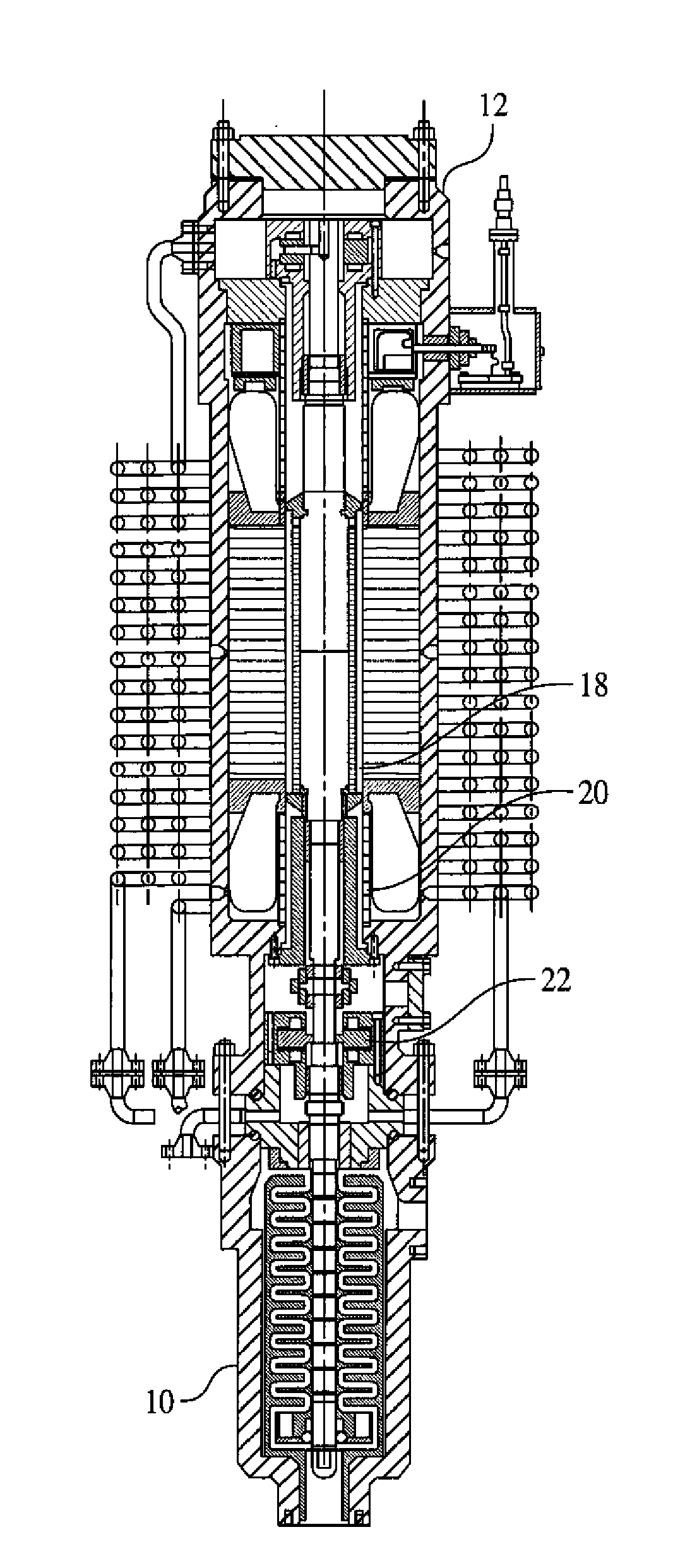
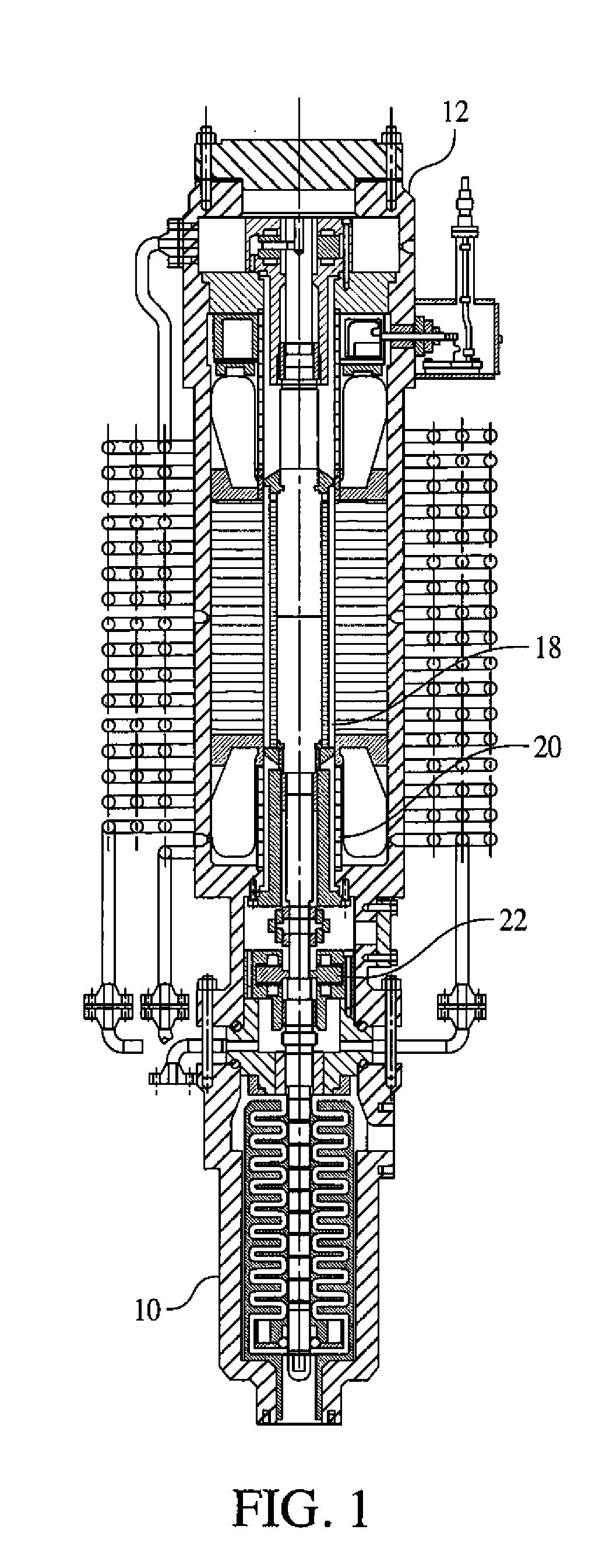
[0015]It is to be understood that the FIGS. and descriptions of the invention have been simplified to illustrate elements that are relevant for a clear understanding of the invention, while eliminating, for purposes of clarity, other elements that may be well known. Those of ordinary skill in the art will recognize that, such as, for example, all of the components of the canned motor pumps other than as shown in the FIGS. have not been described in detail herein for the purpose of simplifying the specification of the patent application.

[0016]For purposes of the description hereinafter, the terms “upper”, “lower”, “vertical”, “horizontal”, “axial”, “top”, “bottom”, “aft”, “behind”, and derivatives thereof shall relate to the invention, as it is oriented in the drawing FIGS. However, it is to be understood that the invention may assume various alternative configurations except where expressly specified to the contrary. It is also to be understood that the specific elements illustrated...


PUM


Abstract

A combined canned motor-pump operates directly in the process fluid without the need for shaft seals or buffer or lubricating fluids. The pump incorporates an integral gas-separating system that includes gas separating hydraulics and a flow path that returns the gas to the main gas / oil separator. The gas-separating system includes a pump inlet for accepting incoming multiphase flow, at least one blade rotatable about the axis of rotation, an open annulus region for separating gas from liquid in the multiphase flow, at least one radial hole in the shaft for directing separated gas to the axial hole, and a pump outlet for discharging liquid from the pump.

Description

CROSS-REFERENCE TO RELATED APPLICATION[0001]This application claims the benefit under 35 U.S.C. §119(e) of the earlier filing date of U.S. Provisional Application Ser. No. 61 / 175,978 filed on May 6, 2009, the contents of which are hereby incorporated by reference.FIELD OF INVENTION[0002]The invention relates generally to a multistage centrifugal pump with a canned motor and a suction gas separation system for multiphase flow handling for use in multiphase flow systems such as subsea separator systems.BACKGROUND OF THE INVENTION[0003]Subsea multiphase pump technologies are presently in operation at several locations around the world. Two known technologies are helico-axial and twin screw pumps.[0004]Helico-axial pumps are rotordynamic type pumps that have been developed specifically for multiphase pumping, and can handle flows of all-liquid or with high gas volume fraction without a reduction in capacity. A typical helico-axial stage consists of an axial flow impeller of helical blad...

Claims


Application Information

Patent Timeline
Patent Type & Authority Applications(United States)
IPC IPC(8): F04B23/08F04B35/04
CPCF04D31/00E21B43/36F04D9/003F04D13/086
Inventor SLOTEMAN, DONALD P.CAMPEN, CLIFF H.CONAWAY, ERIC S.
Owner CURTISS WRIGHT ELECTRO MECHANICAL
Why Eureka
Try Eureka