Process-window aware detection and correction of lithographic printing issues at mask level

a technology of lithographic printing and masks, applied in error detection/correction, instruments, computing, etc., can solve problems such as critical failure models and undesired bridging, and achieve the effects of high precision, high accuracy, and easy handling

Active Publication Date: 2010-11-18
NXP BV
View PDF6 Cites 11 Cited by
  • Summary
  • Abstract
  • Description
  • Claims
  • Application Information

AI Technical Summary

Benefits of technology

[0031]Some embodiments are more elaborate in the classification of the optical-parameter space. In one embodiment, classifying the optical-parameter space comprises, after scanning the test-print-simulation data for the presence of print-failures, ascertaining a criticality-indicator value, which is indicative of a respective degree of criticality of a print of the critical feature according to the print-failure criterion. The criticality-indicator value of this embodiment depends on a detected presence or absence of a print-failure at the sampling point of the process window and on the trend of the geometrical parameter of the test pattern predicted by the failure rule when moving to at least one different process window point. The use of a numerical criticality indicator allows a differentiating between a selectable, in principle arbitrary number of levels of criticality and provides a definition of a threshold of criticality regarding print failure that is easy to handle. Consequently, classifying the optical-parameter space preferably includes differentiating regions in the optical-parameter space according to different criticality indicator va

Problems solved by technology

The critical-failure model relates to a potential printing failure of a critical feature in a physical layout of a print pattern.
Another example of

Method used


Image

  • Process-window aware detection and correction of lithographic printing issues at mask level
  • Process-window aware detection and correction of lithographic printing issues at mask level
  • Process-window aware detection and correction of lithographic printing issues at mask level

Examples


Embodiment Construction

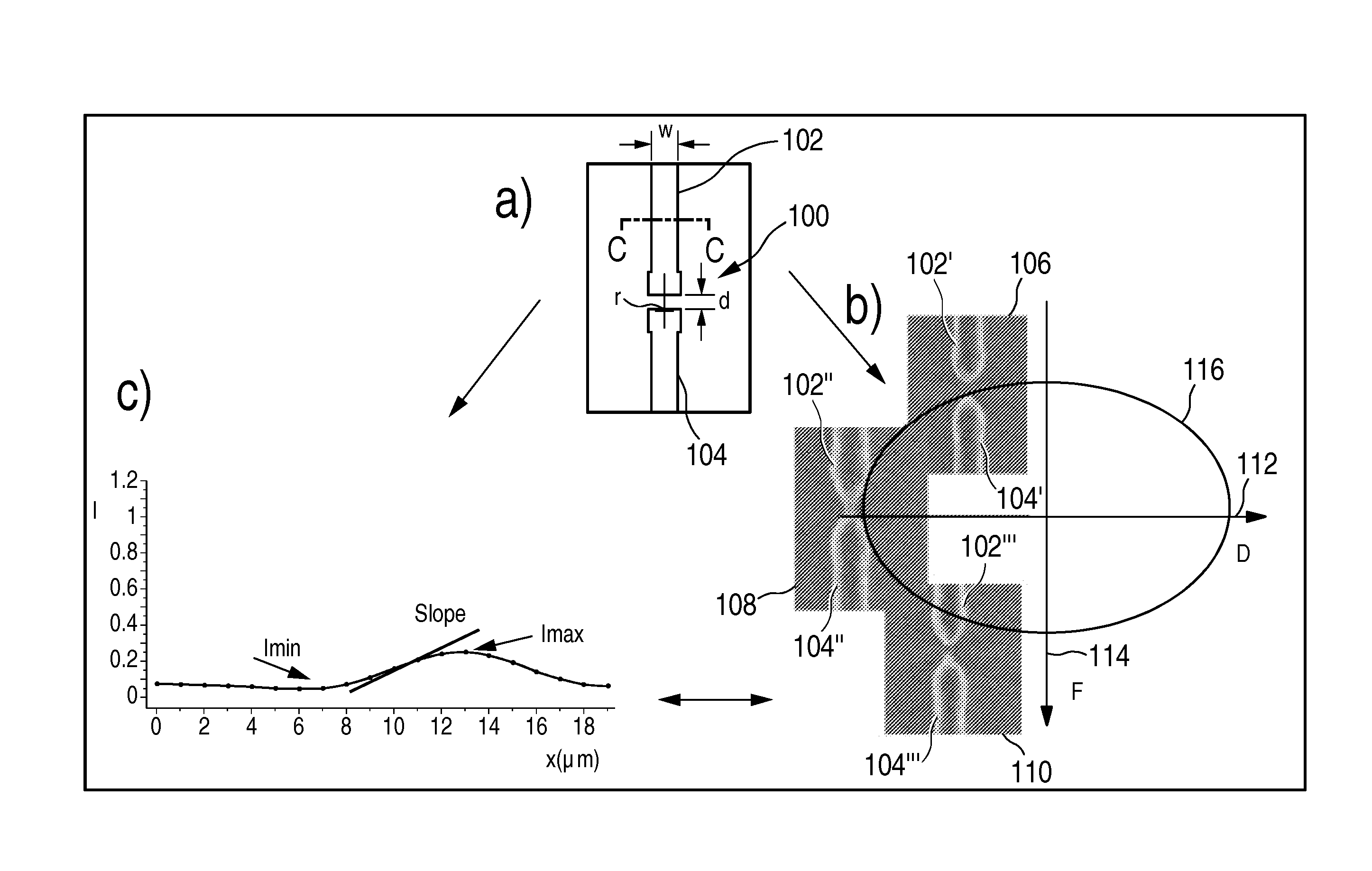
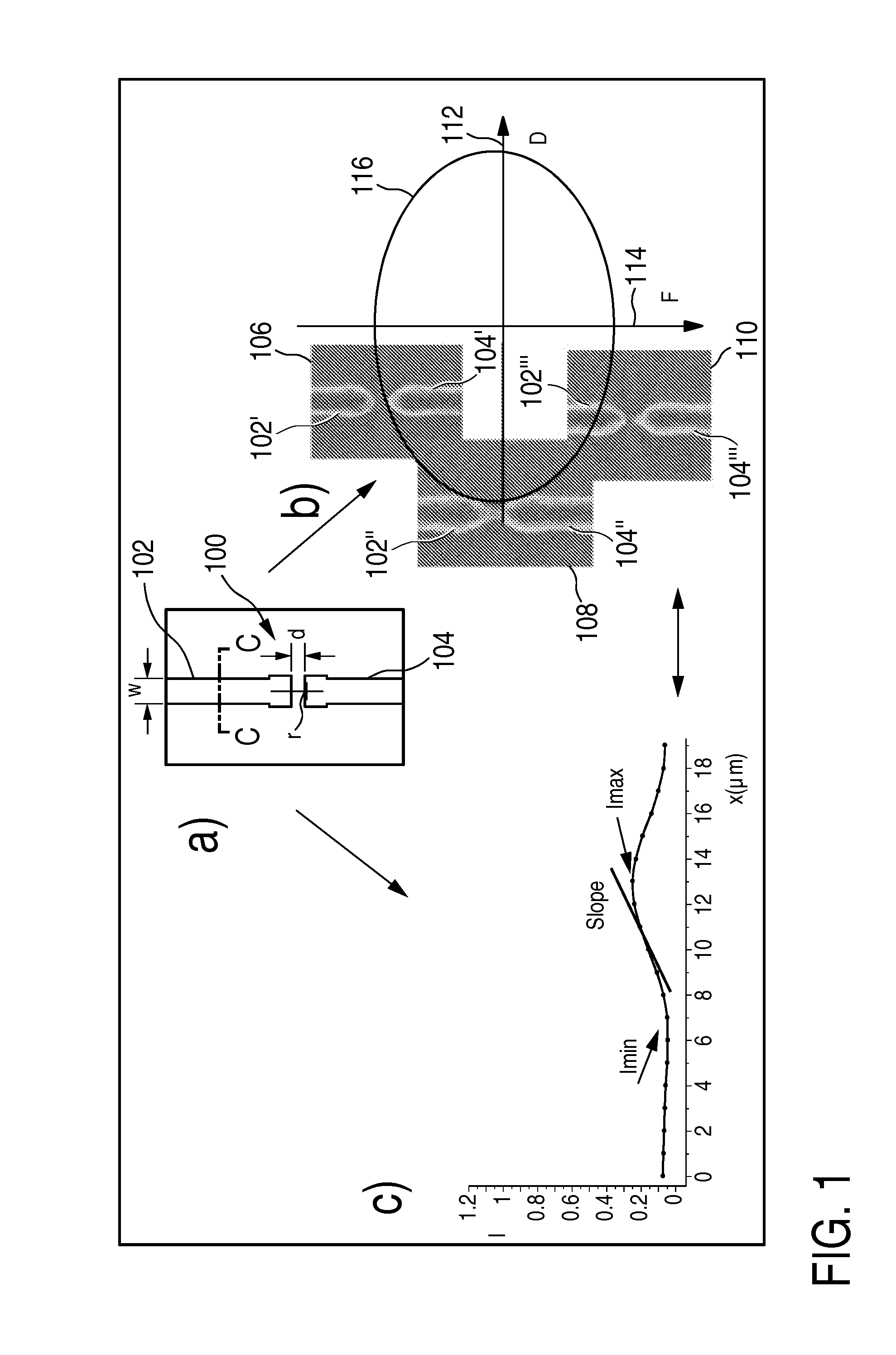
[0086]FIG. 1 shows an illustration of a critical feature in FIG. 1a), different prints of the critical feature at different respective process conditions within a process window in a schematic diagram in FIG. 1b), and an intensity contour along a line c-c in FIG. 1a) in a print of the critical feature, for illustration of an optical-parameter set. FIG. 1 serves to illustrate the technical context of the invention and certain terms used in the present application.

[0087]FIG. 1a) represents, by way of an illustrative example, a critical feature 100 in a physical layout of a print pattern. The critical feature in this example is formed by two line segments 102 and 104 of a material, for instance silicon, which are to be deposited on a substrate, for instance a silicon wafer by means of a photolithographic technique. Both line segments have a width w, which is slightly increased towards the respective line-segment end in comparison with other sections of the line segment. The line-segmen...


PUM


Abstract

In one aspect of the invention, a method provides a calibrated critical-failure model for a printing process of a critical feature by virtue of a classification of an optical parameter space according to at least two print-criticality levels. Print failure of a respective critical feature is judged on the basis of a print-failure criterion for the critical feature. The respective print-criticality level is ascertained from test-print-simulation data at a sampling point of a process window for a given point in an optical-parameter space, and from a failure rule. An advantage achieved with the method is that it comprises ascertaining the predefined optical-parameter set from the test-print-simulation data at only one sampling point of the process window, which sampling point is identical for all test patterns. This saves processing time and processing complexity by reducing the number of ascertained optical-parameter sets and their processing in the subsequent scanning and classifying steps.

Description

FIELD OF THE INVENTION[0001]The present invention relates to a method and apparatus for calibrating a critical-failure model regarding a printing failure of a critical feature in a physical layout of a print pattern. It also relates to a method and apparatus for correcting a critical feature in a physical layout of a print pattern, and to an apparatus for designing a physical layout of an integrated circuit. Finally, the invention relates to a carrier medium and to a computer program for use in the above context.BACKGROUND OF THE INVENTION[0002]The design of highly integrated circuits follows a path from an abstract description of the integrated circuit, for instance in a hardware description language such as VHDL, to a physical layout. The physical layout defines geometrical parameters of device elements of the integrated circuit. The device elements may be defined by polygon-based structures to be fabricated on a wafer.[0003]The wafer fabrication comprises lithographic steps, in w...

Claims


Application Information

Patent Timeline
IPC IPC(8): G06F11/28
CPCG03F1/36G03F1/144
Inventor BORJON, AMANDINE
Owner NXP BV
Why Eureka
Try Eureka