Display device and electronic unit

a technology of electronic units and display devices, applied in the field of display devices and electronic units, can solve the problems of low design flexibility, limited placement positions, and practically difficult incorporation into mobile units, and achieve the effect of reducing any possible deterioration of image quality and favorable simplified configuration

Active Publication Date: 2010-11-25
JAPAN DISPLAY WEST
View PDF5 Cites 135 Cited by
  • Summary
  • Abstract
  • Description
  • Claims
  • Application Information

AI Technical Summary

Benefits of technology

[0008]In consideration thereof, in addition to a common electrode provided originally for application of a display drive voltage, a touch detection electrode may be newly provided for forming a capacitor with the common electrode. The resulting display device is with a capacitance-type touch sensor of a new configuration. This technique is considered as a possibility because the capacitor is changed depending on whether there is any object touch, and by using the display drive voltage to be applied by a display control circuit to the common electrode (also) as a touch-sensor drive signal, the touch detection electrode provides a detection signal responding to any change of the capacitor. The resulting detection signal is then input to any predetermined touch detection circuit, thereby being able to detect any object touch. This technique indeed leads to a touch-sensor-provided display device suitable for the use with a mobile unit whose potential is often unstable. Such a resulting touch-sensor-provided display device is also high in design flexibility considering the type of a display functional layer, and has advantages of easing the integration of circuits, i.e., the integration on a single circuit board between a circuit for display use and a circuit for sensor use.
[0013]Still further, with the display device provided with a capacitance-type touch sensor of the new configuration as above, as already described in the foregoing, a write waveform in a display panel is used for position detection. Therefore, considering the aperture ratio, the manufacturing process, and others, there is a difficulty in providing the shielding layer in an effective display area for eliminating the noise resulted from the writing operation of the image signals.
[0014]As such, the previous capacitance-type touch sensor has had a difficulty in, without using a shielding layer, eliminating any noise (internal noise) resulted from the writing operation of the image signals, and in increasing the accuracy of object detection.
[0015]There is a need for a display device provided with a capacitance-type touch sensor with which the accuracy of object detection can be increased without using a shielding layer, and an electronic unit provided with such a display device.
[0018]In the display device and the electronic unit according to the embodiments of the invention, the capacitor is formed between the common electrode provided originally for application of the common drive voltage and touch detection electrode which is newly provided. This capacitor is changed depending on whether there is any object touch. Accordingly, by utilizing (in a shared fashion) the common drive voltage to be applied by the display control circuit to the common electrode also as a touch-sensor drive signal, the touch detection electrode provides the detection signal responding to any change of the capacitor. The resulting detection signal is then input to the touch detection circuit, thereby being able to detect a position of touch of the object (for example, a factor such as presence or absence of touch by the object). In this configuration, the touch detection circuit corrects the detection signal based on the gray scale of the image signal at the time of acquisition of the detection signal, and performs the detection operation. The detection operation can be thus performed with a reduced influence of noise (internal noise) included in the detection signal due to the writing operation of the image signal during image display control.
[0019]According to the display device and the electronic unit of the embodiments of the invention, the detection operation of detecting the external proximity object is performed based on the detection signal obtained from the touch detection electrode in response to the common drive voltage applied to the common electrode (based on the change in the capacitor), and the detection signal is corrected based on the gray scale of the image signal at the time of acquisition of the detection signal and the detection operation is performed, in the touch detection circuit. The detection operation can be thus performed with a reduced influence of the internal noise without using a shielding layer as have previously been used. Therefore, it is possible to increase the accuracy of object detection in the display device provided with such a capacitance-type touch sensor without using a shielding layer.

Problems solved by technology

As such, such a liquid crystal display element as above may be incorporated with no problem into a fixed television receiver whose power supply comes from wall outlets, for example, but incorporation into a mobile unit is practically difficult.
Also with the above technologies, it is necessary to bring the conductive film for touch sensor use very close to a user's finger(s), and this resultantly imposes restrictions in terms of placement position thereof, e.g., the conductive film for touch sensor use is not allowed to be positioned deep inside the liquid crystal display element.
That is, the design flexibility is low.
This results in a difficulty in the integration of circuits in the device in its entirety.
S56-500230 above, and that of the new configuration as above, however, there is a problem that noise (internal noise) is added to a detection signal as a result of the writing operation of pixel signals (image signals) to display elements on a pixel basis.

Method used


Image

  • Display device and electronic unit
  • Display device and electronic unit
  • Display device and electronic unit

Examples


first embodiment (

1. First Embodiment (exemplary method for internal noise elimination utilizing image signals during display)

[0054]Modified Example (exemplary method for internal noise calculation utilizing blanking period)

second embodiment (

2. Second Embodiment (exemplary use of liquid crystal elements in lateral electric field mode as display elements)

application examples (

3. Application Examples (application examples to electronic unit including touch-sensor-provided display device)

4. Other Modified Examples

[Basic Principles of Touch Detection]

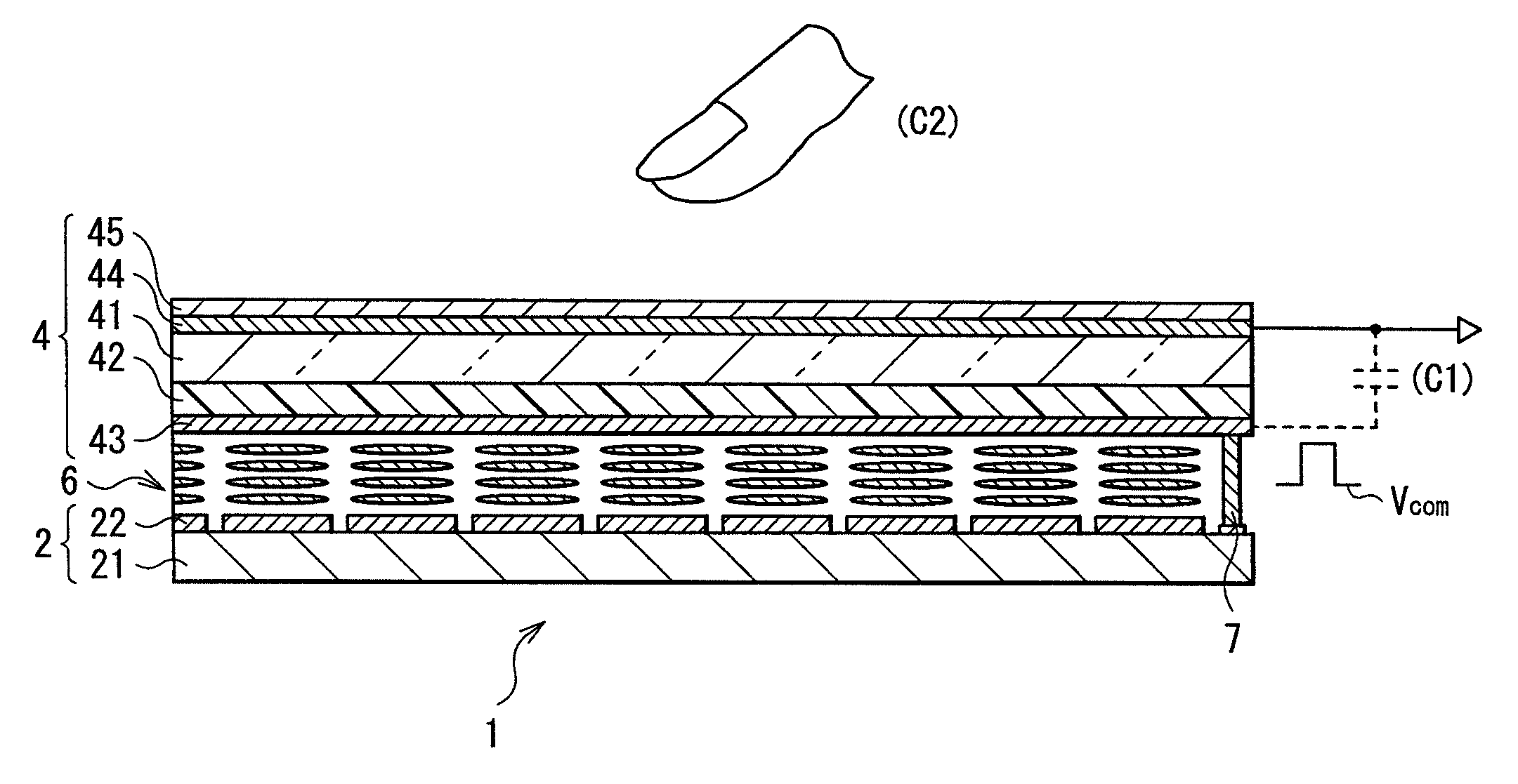
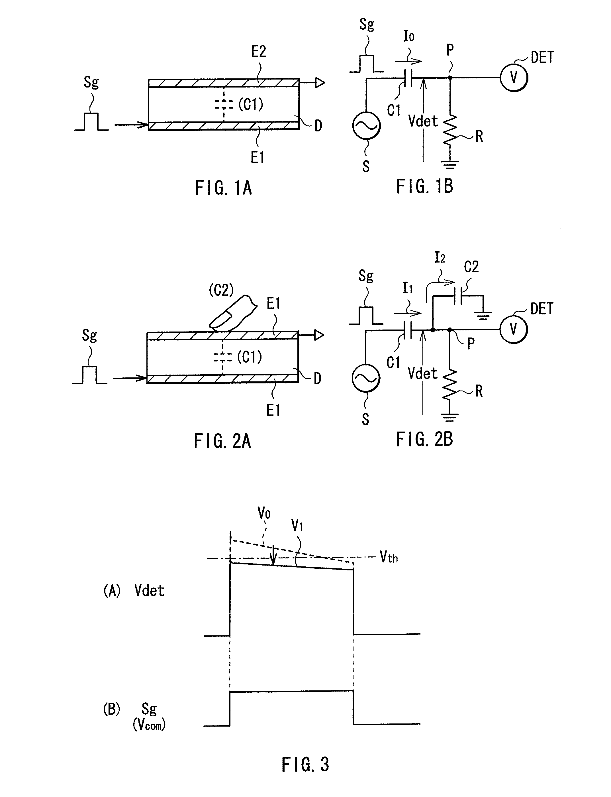
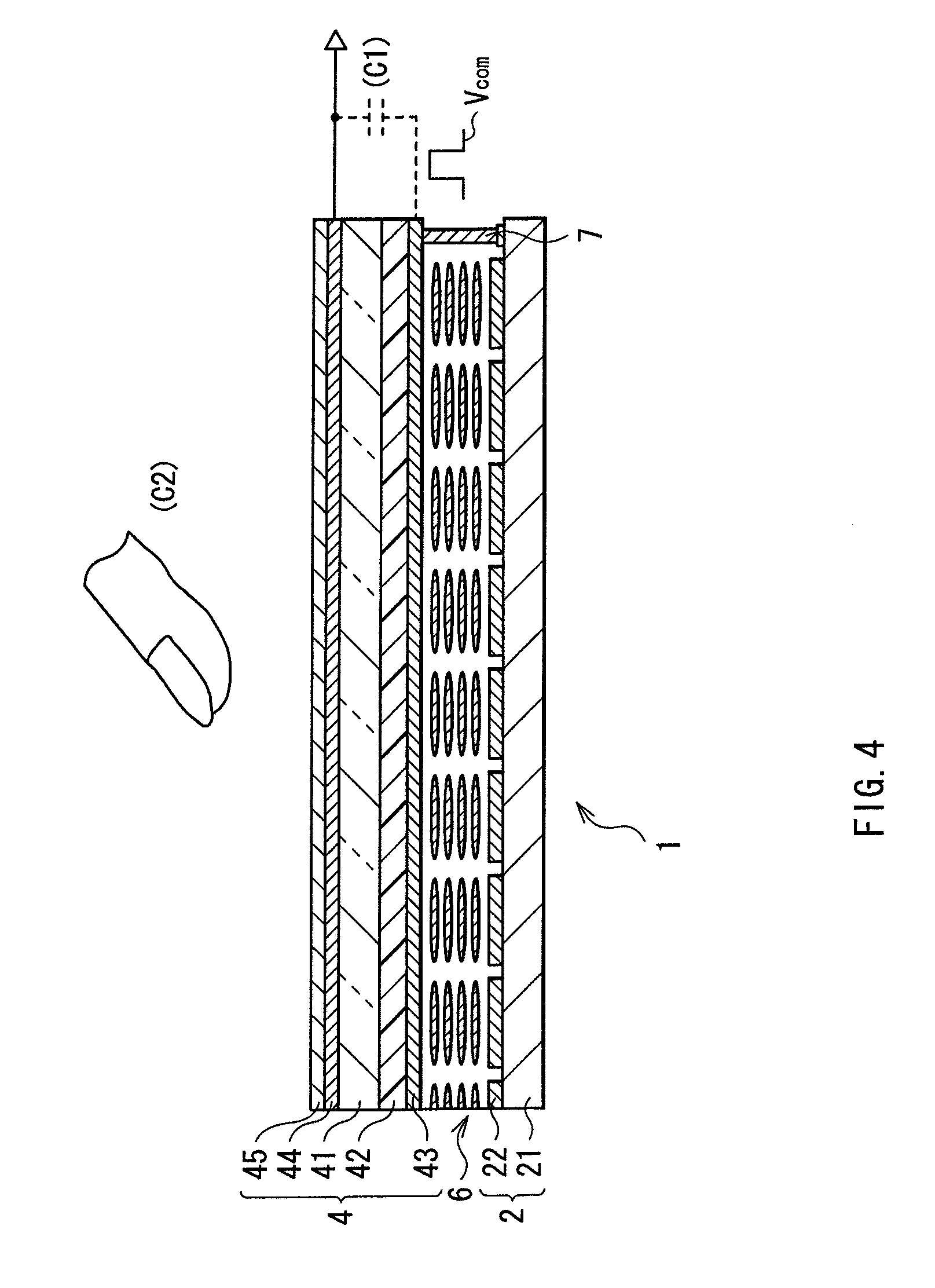
[0055]First of all, by referring to FIGS. 1A to 3, described are the basic principles of touch detection in touch-sensor-provided display devices according to embodiments of the invention. This touch detection is embodied as a capacitance-type touch sensor, which configures a capacitor element using a pair of electrodes (drive electrode E1 and detection electrode E2) as exemplarily shown in FIG. 1A. The pair of electrodes are so disposed as to oppose to each other with a dielectric D sandwiched therebetween. The configuration is illustrated as an equivalent circuit of FIG. 1B. The above components, i.e., the drive electrode E1, the detection electrode E2, and the dielectric D, configure a capacitor element C1. As for the capacitor element C1, one end is connected to an alternating-current (AC) signal source (dr...


PUM


Abstract

The display device with high detection accuracy includes: display pixel electrodes; a common electrode; a display function layer; a display control circuit performing image display control by applying a pixel voltage to each of the display pixel electrodes and applying a common drive voltage to the common electrode, the common drive voltage inverting in synchronization with a drive cycle of the image display control; a touch detection electrode cooperating with the common electrode to form a capacitor; and a touch detection circuit detecting an external proximity object, based on a detection signal obtained from the touch detection electrode in response to the common drive voltage applied to the common electrode. The touch detection circuit corrects the detection signal based on a gray scale of the image signal at the time of acquisition of the detection signal, and performs the detection operation.

Description

[0001]The present application claims priority to Japanese Patent Application JP 2009-123261 filed in the Japanese Patent Office on May 21, 2009, the entire content of which is hereby incorporated by reference.BACKGROUND OF THE INVENTION[0002]1. Field of the Invention[0003]The present invention relates to a display device including a liquid crystal display device and others, and particularly to a display device provided with a capacitance-type touch sensor that allows information input by a user's touch with his or her finger and others, and to an electronic unit provided therein with such a display device.[0004]2. Description of the Related Art[0005]A display device not using general pushbuttons as have previously been used for information input is recently receiving attention. Such a display device is exemplified by a liquid crystal display device, which is mounted directly thereon with a touch detection device generally called a touch panel. Hereinafter, such a touch detection dev...

Claims


Application Information

Patent Timeline
Patent Type & Authority Applications(United States)
IPC IPC(8): G06F3/042
CPCG02F1/13338G02F2001/134372G09G3/3648G06F3/0412G06F3/044G02F2201/121G06F3/0445G06F3/0446G02F1/134372G09G3/3611G09G5/18G09G2300/0426
Inventor NOGUCHI, KOUJINAKANISHI, TAKAYUKIISHIZAKI, KOJITAKEUCHI, TAKEYATERANISHI, YASUYUKI
Owner JAPAN DISPLAY WEST
Why Eureka
Try Eureka