Piezoelectric power converter

a technology of power supply converter and piezoelectric power supply, which is applied in the direction of power conversion system, dc-dc conversion, instruments, etc., can solve the problems of insufficient power transmission efficiency, high cost, and high risk of fire, and achieve low voltage endurance and reliability high

Active Publication Date: 2010-11-25
MIDAS WEI TRADING +1
View PDF3 Cites 0 Cited by
  • Summary
  • Abstract
  • Description
  • Claims
  • Application Information

AI Technical Summary

Benefits of technology

[0007]A major objective of the present invention is to provide a piezoelectric power supply converter, wherein, simple structure piezoelectric elements are utilized in cooperation of an ordinary transformer, for providing output power of several folds, hereby achieving the results of large power output.
[0008]Another objective of the present invention is to provide a piezoelectric power supply converter, wherein, simple structure piezoelectric elements are utilized in replacing ordinary capacitors. Since for a piezoelectric element, its leakage current is small, its voltage endurance is high, without the danger of catching fire induced by overheat, thus its reliability is high, as such, it can be used to solve the problem of fire hazard of the conventional power supply converter due to its low voltage endurance and overheating as caused by the capacitor contained therein. In addition, due to its compact size and thin package profile, the piezoelectric elements have a very good advantage in market competition.

Problems solved by technology

This requirement of customer has put circuit design engineer into a dilemma: it must be able to provide much more power to the system and more sets of voltages, yet the space occupied by the power supply equipment and the battery of the portable electronic device has to be reduced steadily.
In order to fulfill all these technical requirements, a design engineer must adopt power supply of higher efficiency, however, in a circuit of an ordinary power supply converter, an ordinary capacitor is connected to an inductor in series or in parallel in realizing resonance effect, however, in case that the voltage of an input signal to an ordinary capacitor is overly large, that would cause pretty large leakage current, thus the efficiency of power transmission is not quite satisfactory.
In addition, the voltage endurance of the ordinary capacitor is not sufficient, thus operation failure will result in the explosion of a capacitor, and that is liable to lead to hazards of catching fire.
Therefore, the functions and performance of convention power supply converter is not quite satisfactory, and it has much room for improvement

Method used


Image

  • Piezoelectric power converter
  • Piezoelectric power converter
  • Piezoelectric power converter

Examples


first embodiment

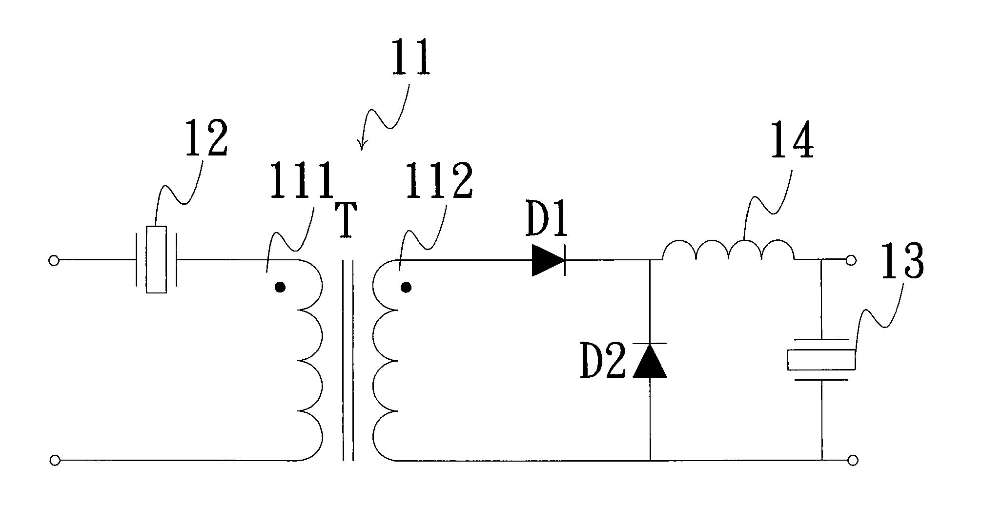
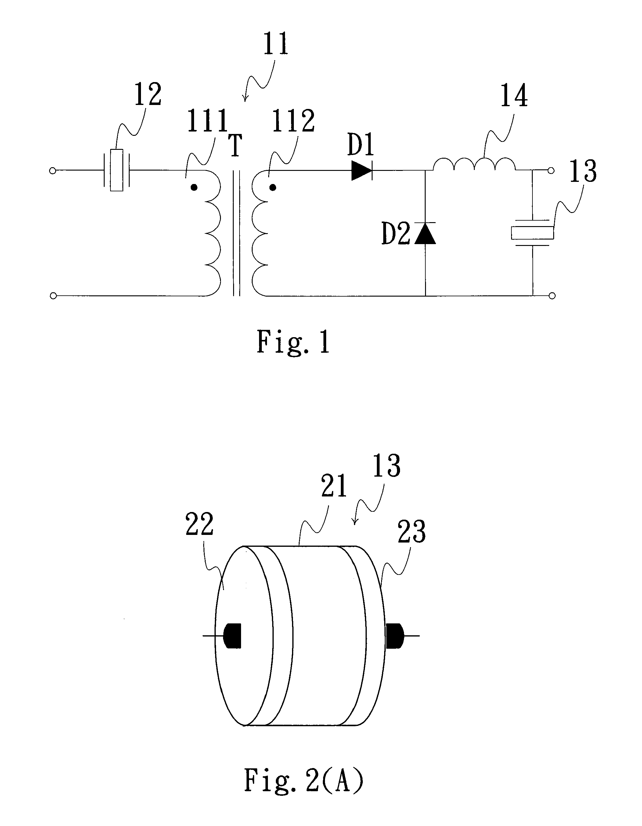
[0036]Firstly, refer to FIG. 1 for a schematic diagram of a piezoelectric power supply converter used in half-bridge input according to the present invention. As shown in FIG. 1, the piezoelectric power supply converter includes: a transformer 11, at least a first piezoelectric element and at least a second piezoelectric element. Wherein, the transformer 11 is provided with a primary side 111 and a secondary side 112. The primary side of the transformer 11 is utilized as an inductor, and it is connected in series with the first piezoelectric element to form a resonance circuit; while the intrinsic capacitance of the first piezoelectric element is utilized as piezoelectric-oscillator 12, and that is used to replace a capacitor in a conventional power supply converter. Wherein, the piezoelectric-oscillator 12 disclosed in the present embodiment as shown in FIG. 2(A), is formed by a substrate 21 of circular plate shape made of piezoelectric material. Of course, its shape can be square ...

ninth embodiment

[0048]Moreover, refer to FIG. 11 for a schematic diagram of a piezoelectric power supply converter used in half-bridge input according to the present invention, wherein, a first resonance inductor 51 is connected to a an insulating piezoelectric-oscillator 91, hereby forming a full-bridge resonance circuit, and is located on a primary side 111 of a transformer 11. Wherein, when the resonance circuit resonances, the insulating piezoelectric-oscillator 91 is made to produce the piezoelectric effect to raise the capacitance and output it to the primary side 111, and that is used to provide a smaller output power to an outside load in performing the operations required.

[0049]In the embodiments mentioned above, only one voltage output to an outside load is designed in performing the operations required, in case that the input voltage signal is much more larger, then more than two outputs can be designed. In other words, more than two center taps must be provided in cooperation with more ...


PUM


Abstract

Disclosed is a piezoelectric power supply converter, wherein, a piezoelectric element is utilized to replace a conventional capacitor, due to characteristic of mechanical resonance of said piezoelectric element, said piezoelectric element may contain higher capacitance than said conventional capacitor, and a parasitic resistance of said piezoelectric element is smaller that that of an ordinary capacitor. Through a resonance between an externally added inductive element and a piezoelectric-capacitor and said resonance of said piezoelectric element itself, said piezoelectric element is capable of transmitting electrical energy efficiently, thus achieving large output power. Therefore, said piezoelectric-capacitor is capable of improving shortcomings of said conventional capacitors of low voltage endurance, large leakage current, and small output power.

Description

BACKGROUND OF THE INVENTION[0001]1. Field of the Invention[0002]The present invention relates to a piezoelectric power supply converter, and in particular to a power supply converter capable of raising its output power by means of piezoelectric elements.[0003]2. The Prior Arts[0004]Nowadays, more and more portable electronic devices are capable of providing various advanced functions, for example, color screen, stereo audio, hyper links, such as GPRS, wireless network, and Bluetooth, and photo & video recording, Contrast to the existing voluminous and cumbersome portable electronic devices, what the consumers require is that, product design has to be not only of compact size, thin profile, light weight, and easy to operate, but the battery must also be able to provide power for enough long period of operation. This requirement of customer has put circuit design engineer into a dilemma: it must be able to provide much more power to the system and more sets of voltages, yet the space ...

Claims


Application Information

Patent Timeline
Patent Type & Authority Applications(United States)
IPC IPC(8): H02M3/24
CPCH02M3/33569H02M3/33573H02M3/33571H02M3/01H02M3/28H02M7/48
Inventor WEI, TAO-CHIN
Owner MIDAS WEI TRADING
Why Eureka
Try Eureka