Energy recovery enhanced condenser reactivated desiccant refrigerant dehumidifier

a desiccant refrigerant dehumidifier and energy recovery technology, which is applied in the field of air conditioning and dehumidification equipment, can solve the problems of ice formation problems of coil-based dehumidifier systems, and achieve the effect of reducing the required energy input and low energy consumption

Active Publication Date: 2010-12-09
MANTERS CORP
View PDF16 Cites 29 Cited by
  • Summary
  • Abstract
  • Description
  • Claims
  • Application Information

AI Technical Summary

Benefits of technology

[0014]As compared to conventional air conditioning systems and processes as described above the present invention has significant advantages in treating fresh or outdoor air to supply that air at space temperature and at or below space humidity. The most significant advantage is low energy consumption. More specifically, the present invention reduces the required energy input from 30 to 75% as compared to the other techniques available.

Problems solved by technology

More particularly, coil based dehumidifier systems have problems with ice forming on the evaporator coils as they provide lower coil temperatures in order to provide lower humidity conditions.

Method used


Image

  • Energy recovery enhanced condenser reactivated desiccant refrigerant dehumidifier
  • Energy recovery enhanced condenser reactivated desiccant refrigerant dehumidifier
  • Energy recovery enhanced condenser reactivated desiccant refrigerant dehumidifier

Examples


Embodiment Construction

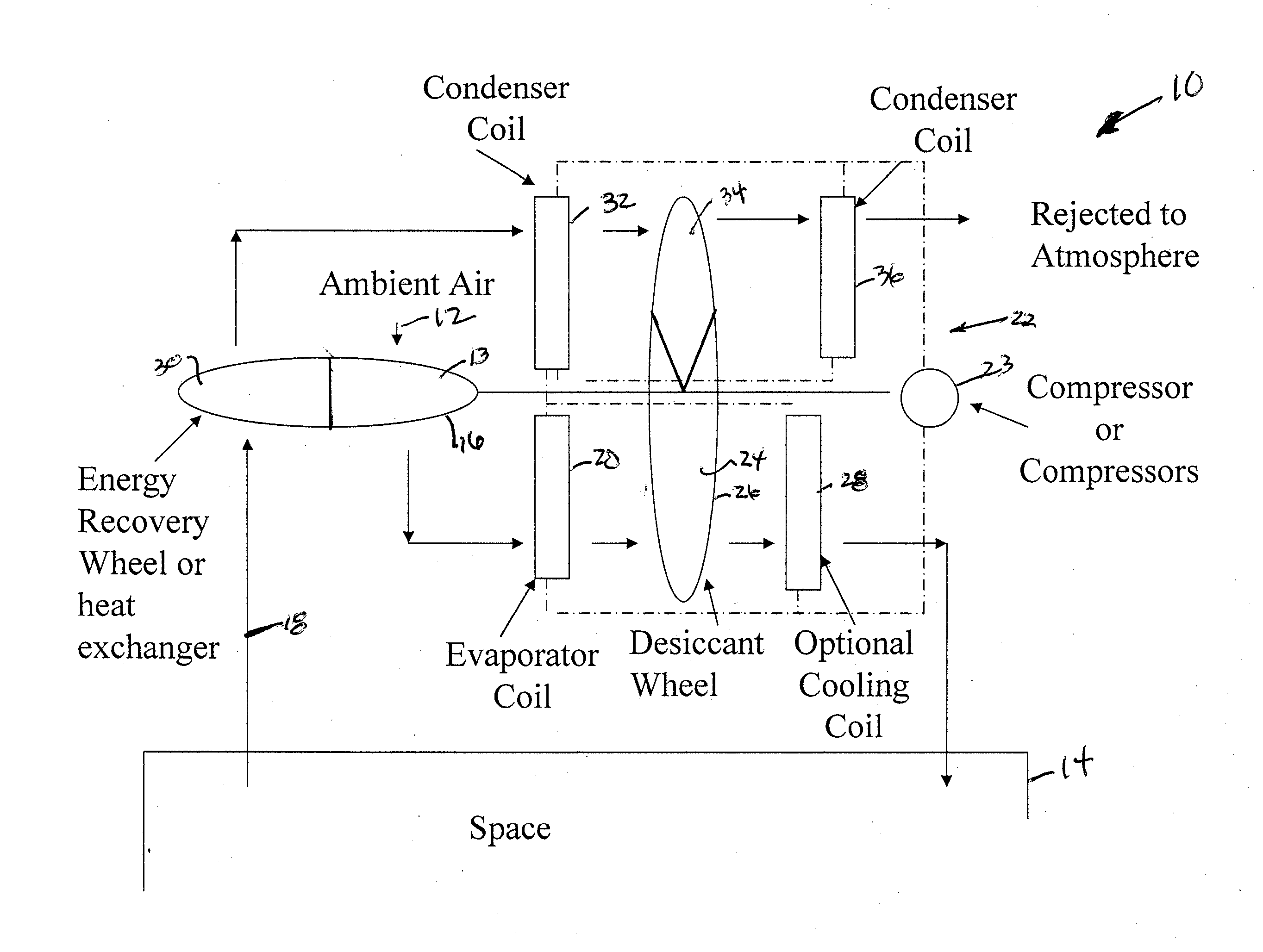
[0041]Referring now to the drawing in detail and initially to FIG. 7, an air conditioning system 10 according to one embodiment of the invention is illustrated in which a stream of ambient air 12 is treated to desired temperature and humidity conditions for use in a room, enclosure or space 14. In the illustrative embodiment, the system is used in areas where the ambient outside air has a high temperature and high humidity content or ratio as described above. FIG. 7 is a schematic drawing and it will be understood by those skilled in the art that the described air streams are contained in appropriate duct work and moved with appropriate fans, which are not illustrated.

[0042]As seen in FIG. 7, fresh, outdoor, ambient supply air 12 is first passed through a section 13 of an energy recovery device 16. The air is cooled and dehumidified as it passes through the energy recovery device 16. As described above, this device may be a conventional rotating enthalpy wheel or other form of heat ...


PUM


Abstract

A method and apparatus for conditioning ambient air for use in an enclosure is disclosed which cools the ambient supply air stream in sensible energy recovery device or cools and dehumidifies the ambient supply air stream in an enthalpy energy recovery device. The thus cooled air is then cooled by a cooling coil of a refrigerant cooling system to reduce its temperature and humidity. The thus cooled and dehumidified air is then passed through a segment of a rotating desiccant wheel or through a different type of desiccant dehumidification device under conditions which reduce its moisture content and increases its temperature. The supply air is then delivered from the desiccant wheel to the enclosure. The desiccant wheel is regenerated by heating a separate regeneration air stream, provided by the exhaust air from the space and using the condensing coil of the refrigerant system to increase the regeneration air stream temperature. The thus heated regeneration air stream is then passed through another segment of the rotating desiccant wheel to regenerate the wheel and is exhausted to the atmosphere.

Description

[0001]This application claims the benefit of U.S. Provisional Patent Application No. 61 / 028,693, filed Feb. 14, 2008, which is incorporated herein by reference in its entirety.BACKGROUND OF THE INVENTIONField of the Invention[0002]The present invention relates to air conditioning and dehumidification equipment, and more particularly to an air conditioning method and apparatus using desiccant dehumidification technology.[0003]It is well known that traditional cooling coil based air conditioning systems do not provide efficient means of dehumidification. Because such systems must provide cooling in order to provide dehumidification, in many cases the cooling is in excess of what is required and the desired enclosure or space is over cooled. If insufficient cooling is supplied the space to be cooled will be under dehumidified. To overcome this problem, reheat coils have been used downstream of the dehumidifying cooling coil. This allows the cooling coil to dehumidify as needed and the ...

Claims


Application Information

Patent Timeline
Patent Type & Authority Applications(United States)
IPC IPC(8): F25D17/06F25B15/00F25B39/02
CPCF24F3/1423F24F12/003F24F2012/007F24F2203/1016F28D19/04F24F2203/1068F24F2203/1084Y02B30/52Y02B30/563F24F2203/1032Y02B30/56Y02B30/12Y02B30/00
Inventor TEIGE, PETERHAYES, MICHAEL
Owner MANTERS CORP
Why Eureka
Try Eureka