
Composite of at least two semiconductor substrates and a production method

a technology of semiconductor substrates and production methods, applied in semiconductor devices, semiconductor/solid-state device details, electrical apparatus, etc., can solve the problems of insufficient bonding strength of connection and relatively high construction of entire composites, and achieve the effect of minimizing the lateral overflow of eutectic over the microstructure and extending the thickness

Inactive Publication Date: 2010-12-09
ROBERT BOSCH GMBH
View PDF3 Cites 2 Cited by
  • Summary
  • Abstract
  • Description
  • Claims
  • Application Information

AI Technical Summary

Benefits of technology

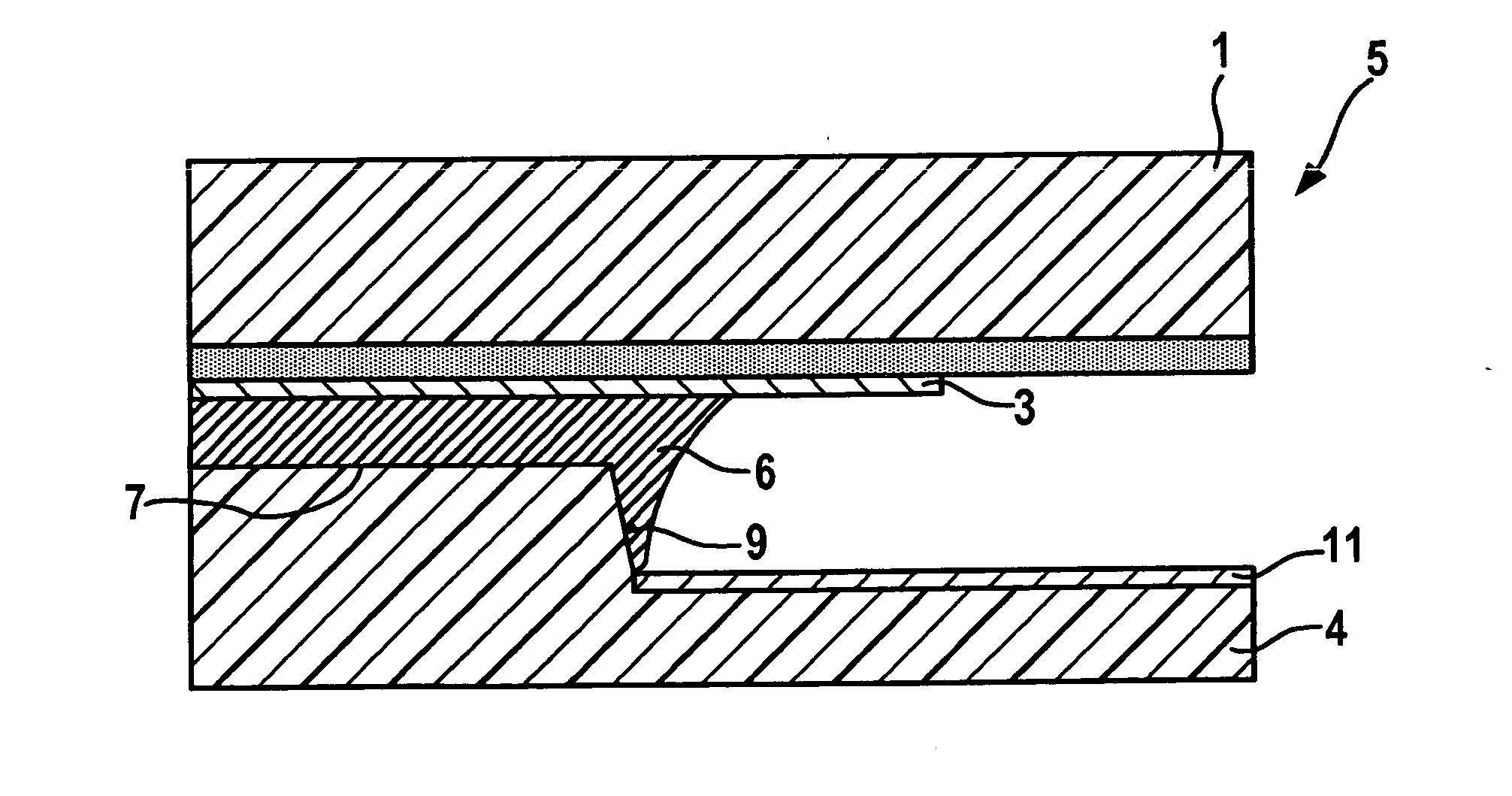
[0008]On the whole, the deposit thickness of the soldering material may be significantly reduced by providing the microstructure. Experiments have shown that the invention allows for firm connections to be produced even when the deposit thickness of the soldering material is reduced by a factor of 5 in comparison with the related art, with the additional advantage that, on the whole, the composite does not build up as high. Enlarging the eutectic layer not only increases the bonding strength of the composite, it also increases the electric conductivity, which means that the soldering material may be used not only to connect the two semiconductor substrates, but also for the electric contacting of active and / or passive electronic components of the semiconductor substrates.
[0014]A specific embodiment is particularly advantageous in which the soldering material not (only) has the job of connecting the at least two semiconductor substrates to each other, but also in which the soldering material is used to produce an electric connection between two passive or active electric components, such as circuit traces or transistors, disposed on different semiconductor substrates. In particular, due to the reduced deposit thickness of the soldering material and the, in comparison to the total thickness of the soldering material, thick eutectic layer, an optimum conductivity is achieved.
[0018]In a development of the exemplary embodiments and / or exemplary methods of the present invention, it is advantageously provided that a material is provided on at least one of the semiconductor substrates, which may be on both semiconductor substrates, and particularly may be in a ring-shaped manner around the soldering material or the formed eutectic layer, which may be vapor-deposited, which does not allow for, or possibly only allows a slight, wetting with liquid eutectic, so that an unchecked lateral overflow of the eutectic over the microstructure is minimized, which may be completely prevented.

Problems solved by technology

A disadvantage of the known method and the composites of at least two semiconductor substrates produced using it is that the bonding strength of the connection is not sufficient for some applications.
In addition, it is a disadvantage that the soldering material has to be deposited relatively thickly, which means that the entire composite is built up relatively high.

Method used


Image

  • Composite of at least two semiconductor substrates and a production method
  • Composite of at least two semiconductor substrates and a production method
  • Composite of at least two semiconductor substrates and a production method

Examples


Embodiment Construction

[0029]Identical components and components having the same function are labeled by the same reference symbols in the figures.

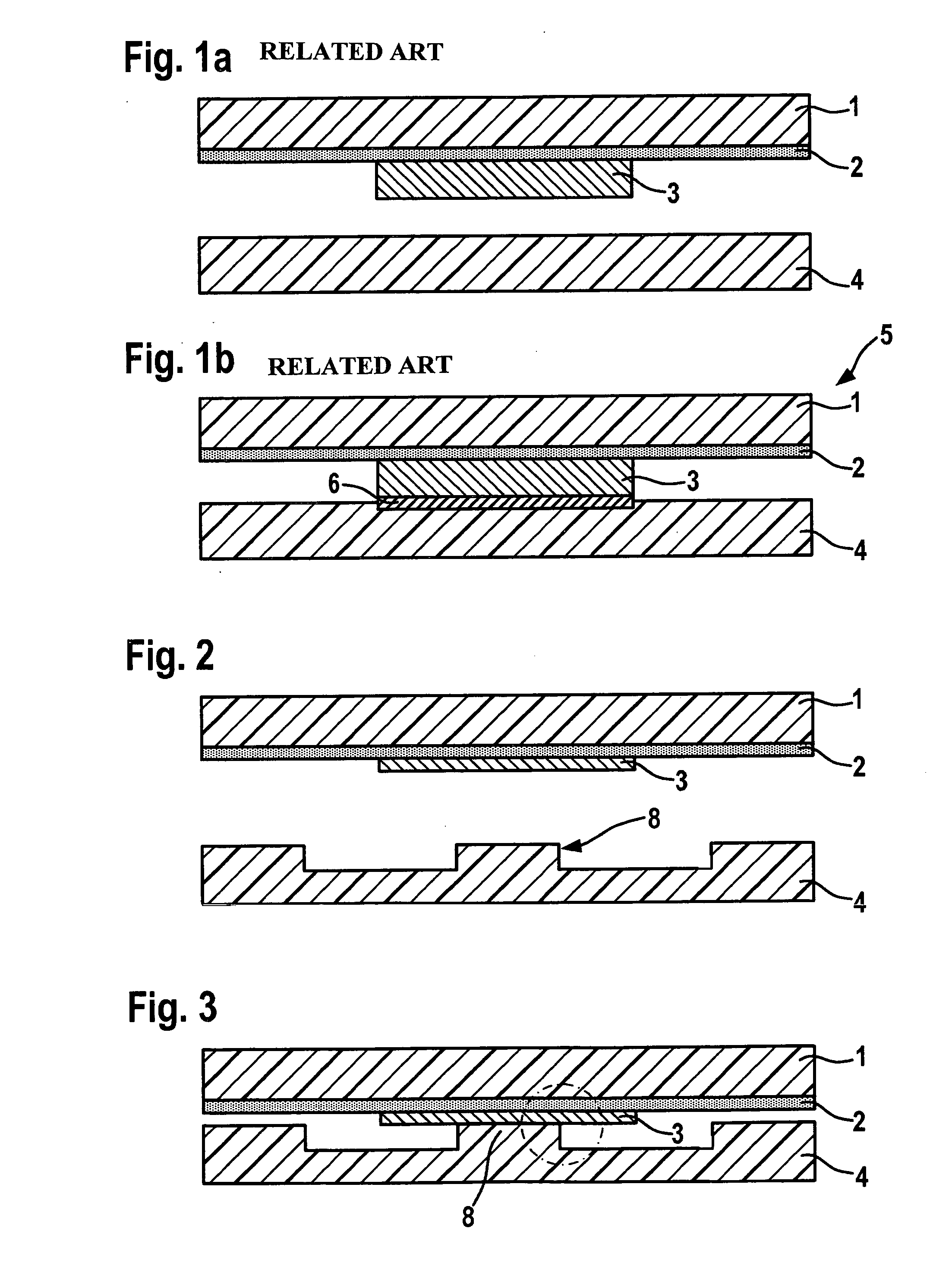
[0030]The related art is illustrated in FIG. 1a and FIG. 1b. A first, flat semiconductor substrate 1 may be seen, in particular a wafer on which an adhesive layer 2 has been vapor-deposited. Soldering material 3, which is used to connect first semiconductor substrate 1 to a second semiconductor substrate 4 disposed in the drawing plane below it, bonds to this planar adhesive layer.

[0031]FIG. 1b illustrates a completely developed, known composite 5, including first semiconductor substrate 1 and second semiconductor substrate 4. It can be seen that between planar second semiconductor substrate 4 and soldering material 3, a thin eutectic 6 has been formed, which is responsible for the connection of second semiconductor substrate 4.

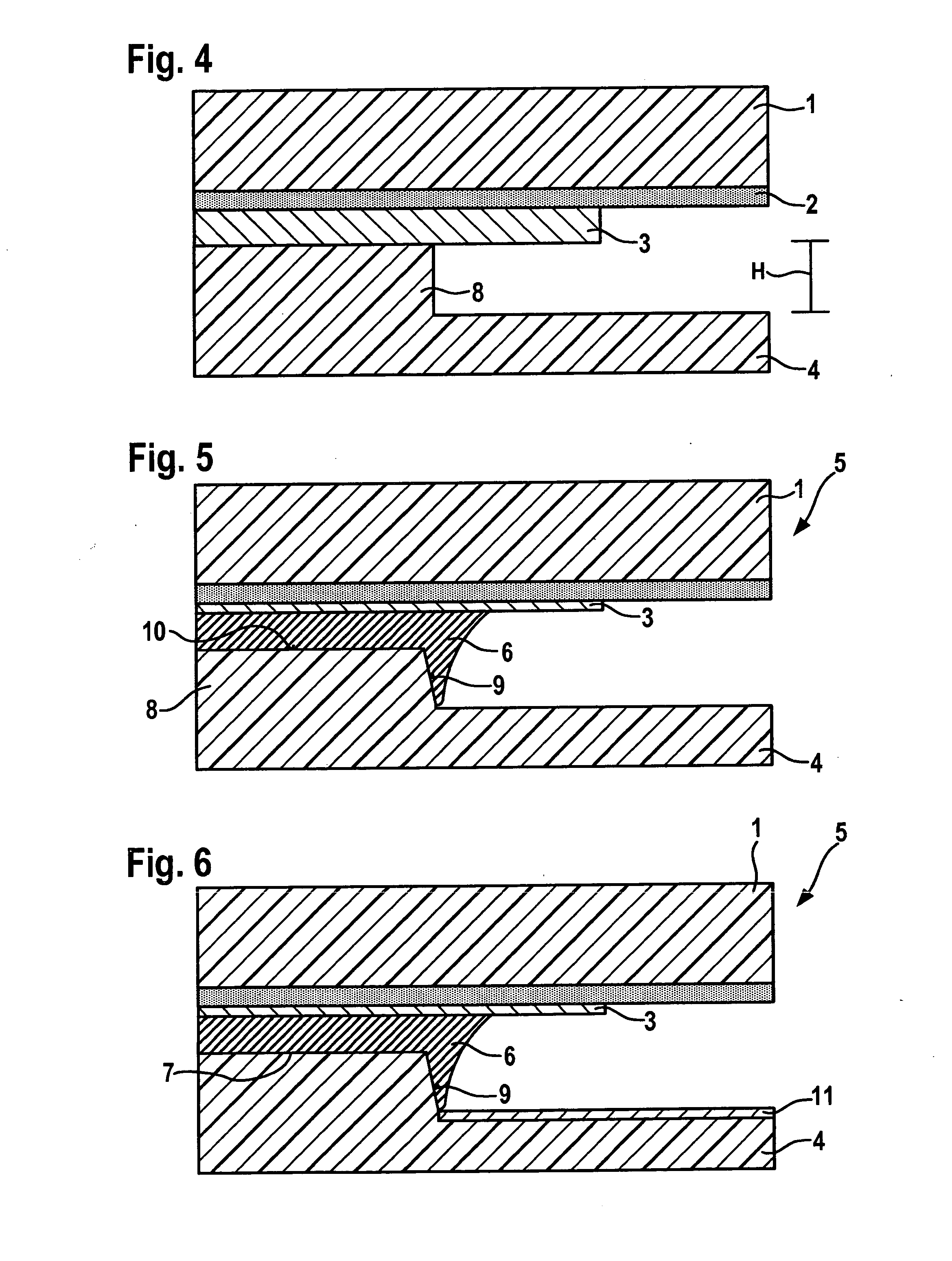
[0032]FIG. 2 illustrates a method step in the production of a composite 5 shown in sections in FIGS. 5 and 6. The upper half of the dra...


PUM

PropertyMeasurementUnit
widthaaaaaaaaaa
widthaaaaaaaaaa
sizeaaaaaaaaaa

Abstract

A composite, including a first semiconductor substrate that is secured by soldering material to at least one second semiconductor substrate, a eutectic being formed between the soldering material and the second semiconductor substrate and / or at least one layer possibly provided on the semiconductor substrate. It is provided that the eutectic is formed between the soldering material and a microstructure, which is formed in the region of contact with the soldering material on the second semiconductor substrate and / or the layer. Also described is a production method.

Description

FIELD OF THE INVENTION[0001]The present invention relates to a composite of at least two semiconductor substrates, as well as a method for producing a composite.BACKGROUND INFORMATION[0002]In semiconductor technology, for example, for producing MEMS (Micro-Electro-Mechanical Systems), it is necessary to firmly connect two semiconductor substrates to each other, for example, in order to encapsulate electronics and / or micromechanics mounted on one of the semiconductor substrates. The use of eutectic bonding connections to connect two semiconductor substrates is known. A thin eutectic is formed between a soldering material and one of the semiconductor substrates, and it is responsible for the firm connection. A disadvantage of the known method and the composites of at least two semiconductor substrates produced using it is that the bonding strength of the connection is not sufficient for some applications. In addition, it is a disadvantage that the soldering material has to be deposite...

Claims


Application Information

Patent Timeline
Patent Type & Authority Applications(United States)
IPC IPC(8): H01L23/488H01L21/768
CPCB81C1/00269B81C2203/0118H01L2924/1461H01L2225/06565H01L2225/06513H01L2225/06555H01L2924/014H01L2924/01033H01L2924/01024H01L2224/83805H01L24/29B81C2203/038H01L21/50H01L23/10H01L24/30H01L24/33H01L24/83H01L24/94H01L25/0657H01L2224/32057H01L2224/32506H01L2224/83385H01L2224/838H01L2924/01013H01L2924/01032H01L2924/01063H01L2924/01079H01L2924/01322H01L2924/14H01L2924/1631H01L2924/164H01L2924/0132H01L2924/01014H01L2924/00
Inventor TRAUTMANN, ACHIMFEYH, ANDO
Owner ROBERT BOSCH GMBH
Learn More