
Wavelength conversion laser

a wavelength conversion laser and wavelength conversion technology, applied in lasers, optics, instruments, etc., can solve the problems of narrow spectral width, dotted pattern interference noise referred to as speckle noise, decrease in conversion efficiency, etc., to achieve high wavelength conversion efficiency, low coherency, and broad spectral width

Inactive Publication Date: 2010-12-09
PANASONIC CORP
View PDF6 Cites 25 Cited by
  • Summary
  • Abstract
  • Description
  • Claims
  • Application Information

AI Technical Summary

Benefits of technology

[0011]An object of the present invention is to provide a compact wavelength conversion laser that has high wavelength conversion efficiency and low coherency over a broad spectral width.

Problems solved by technology

However, in the case of applying to imaging or illumination fields and the like, internal cavity type wavelength conversion lasers have the problems of having a narrow spectral width and the generation of dotted pattern interference noise referred to as speckle noise.
In internal cavity type wavelength conversion lasers, in the case of carrying out multi-mode oscillation with a solid-state laser, there is the problem of a decrease in conversion efficiency.
During high output of a solid-state laser in particular, multi-mode oscillation progresses resulting in a decrease in conversion efficiency.
In addition, in internal cavity type wavelength conversion lasers, wavelength conversion efficiency cannot be freely set to a high level in the manner of the transmittance of a laser exit window since wavelength conversion efficiency is typically low.
Consequently, in order to increase the efficiency of internal cavity type wavelength conversion lasers, it is necessary to reduce internal loss of materials within the cavity, thereby also resulting in the problem of increased material costs.
Since microchip solid-state lasers have a short absorption length for the laser crystal pumping light, those locations of the laser crystals that generate heat become concentrated, thereby decreasing efficiency at high output and causing the problem of instability.
Consequently, temperature regulation is required for stable operation thereby resulting in handling difficulties.
In addition, internal cavity type wavelength conversion lasers generate extremely high levels of mode competition noise referred to as a green problem that occurs due to insertion of a non-linear optical crystal into a laser cavity that carries out multi-mode oscillation, thereby resulting in the problem of unstable output.
However, although the configurations of internal cavity type sum-frequency wave generation using two types of solid-state laser crystals as proposed in the prior art described above allow sum-frequency generation, they are not able to carry out other waveform conversion.
Consequently, waveform converted light of multiple wavelengths cannot be obtained.
In addition, mode competition noise, which is thought to occur during high output and during multiple wavelength oscillation, is not taken into consideration.
Moreover, since the waveform conversion efficiency of internal cavity type waveform conversion lasers it typically low, high waveform conversion efficiency cannot be freely set in the manner of the transmittance of a laser exit window.
Consequently, in order to increase the efficiency of internal cavity type wavelength conversion lasers, it is necessary to reduce internal loss generated from materials within the cavity, thereby resulting in the problem of increased material costs.
In addition, since conventional multi-mode internal cavity type wavelength conversion lasers as described above carry out wavelength conversion independently with each optical axis by oscillating laser light having multiple optical axes, there is the problem of decreased conversion efficiency as compared with wavelength conversion with a single optical axis.
In addition, since it is necessary to have numerous optical axes in order to obtain stability, handling of the outgoing beams becomes difficult.

Method used


Image

  • Wavelength conversion laser
  • Wavelength conversion laser
  • Wavelength conversion laser

Examples


embodiment 1

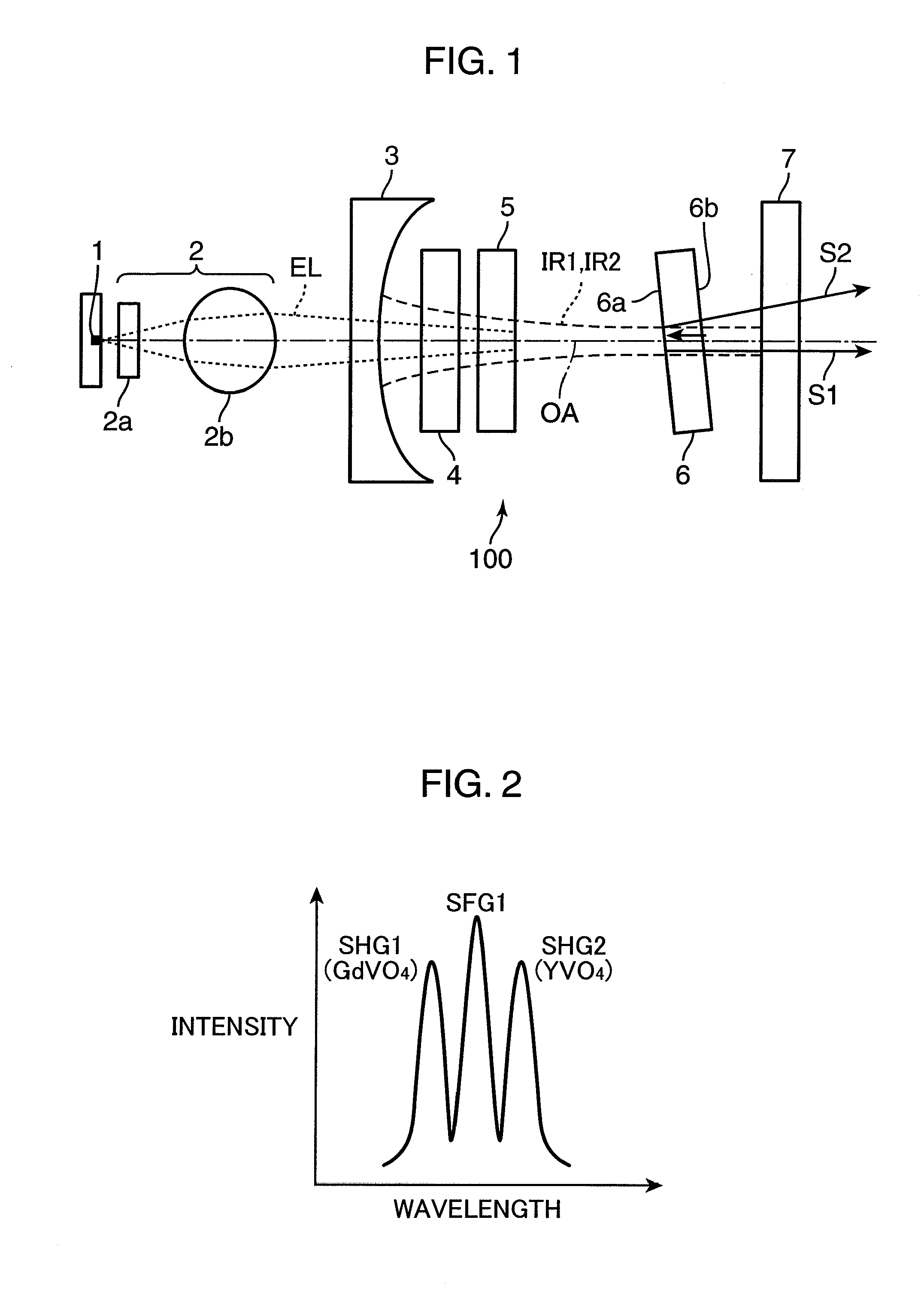
[0041]FIG. 1 is a schematic block diagram of a wavelength conversion laser in Embodiment 1 of the present invention. A wavelength conversion laser 100 shown in FIG. 1 is provided with a pumping laser diode (LD) 1, a focusing optics 2, a concave mirror 3, two laser crystals 4 and 5, a wavelength converting element 6 and a flat mirror 7. Here, a cavity is composed from the concave mirror 3 and the flat mirror 7, a solid-state laser is composed from the concave mirror 3, the two laser crystals 4 and 5 and the flat mirror 7, and the wavelength converting element 6 is arranged within the cavity (between the concave mirror 3 and the flat mirror 7).

[0042]A semiconductor laser in the form of the pumping LD 1 oscillates pumping light EL that pumps the two laser crystals 4 and 5. The focusing optics 2 is composed of a lens 2a, which controls the beam diameter of pumping light EL in the direction of thickness of an active layer of the pumping LD 1, and a lens 2b, which controls the beam diamet...

embodiment 2

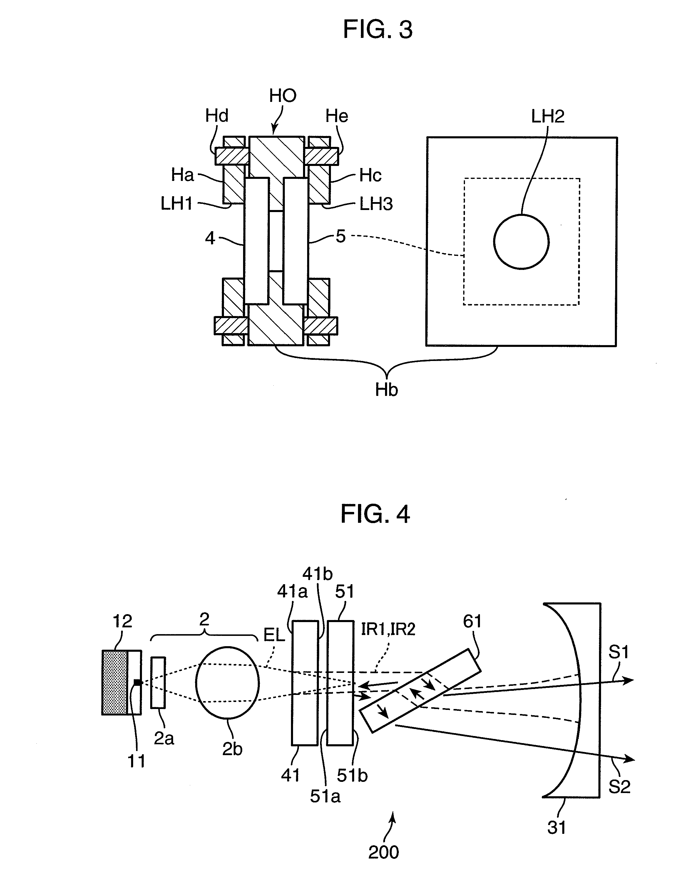
[0082]FIG. 4 is a schematic block diagram of a wavelength conversion laser 200 in an Embodiment 2 of the present invention. Furthermore, in FIG. 4, the same reference symbols are used to indicate those components that are the same as those of Embodiment 1, and detailed explanations thereof are omitted.

[0083]In the wavelength conversion laser 200, the solid-state laser that oscillates at multiple wavelengths is composed of a laser crystal 41, a laser crystal 51 and a concave mirror 31, and the cavity of the solid-state laser is composed of the laser crystal 41 and the concave mirror 31.

[0084]The laser crystal 41 is composed of Nd:GdVO4 (Nd concentration: 0.5%, thickness: 0.6 mm), and oscillates at wavelengths having a central wavelength of 1062.9 nm. The laser crystal 51 is composed of Nd:YVO4 (Nd concentration: 2%, thickness: 1 mm), and oscillates at wavelengths having a central wavelength of 1064.3 nm. Pumping light EL emitted by a pumping LD 11 is focused by the focusing optics 2 ...

embodiment 3

[0096]FIG. 5 is a schematic block diagram of a wavelength conversion laser 300 in an Embodiment 3 of the present invention. Furthermore, in FIG. 5, the same reference symbols are used to indicate those components that are the same as those of previously described embodiments, and detailed explanations thereof are omitted.

[0097]In the wavelength conversion laser 300, a solid-state laser that oscillates at multiple wavelengths is composed of a concave mirror 32, a concave mirror 33, a laser crystal 42, a laser crystal 52, a flat mirror 71 and a flat mirror 72, and a cavity of the solid-state laser is composed of the concave mirror 32 and the concave mirror 33. The laser crystal 42, the laser crystal 52 and a wavelength converting element 62 are arranged within the cavity, while the flat mirrors 71 and 72 serve as output mirrors of converted wavelength light S3 and S4.

[0098]Focusing optics 22 and 23 are composed of lenses 22a and 23a, which control the beam diameter of pumping light EL...


PUM


Abstract

A wavelength conversion laser 100 is provided with a solid-state laser having a cavity, and a wavelength converting element 6 arranged within the cavity. The solid-state laser includes two or more types of laser crystals 4 and 5 and oscillates solid-state laser light of multiple wavelengths. The wavelength converting element 6 converts the solid-state laser light of multiple wavelengths into light of second harmonic waves and sum-frequency wave of multiple wavelengths and simultaneously generates the second harmonic waves and sum-frequency wave of multiple wavelengths. The wavelength conversion laser 100 outputs converted wavelength light having a broad spectral width and low coherency, thereby enabling it to carry out highly efficient and stable high-output oscillation.

Description

TECHNICAL FIELD[0001]The present invention relates to an internal cavity type wavelength conversion laser in which a wavelength converting element is inserted into a cavity of a solid-state laser.BACKGROUND ART[0002]Wavelength conversion lasers have been developed that convert the wavelength of a fundamental wave laser to converted waves such as second harmonic wave (second harmonic generation: SHG), sum-frequency wave (sum frequency generation: SFG) or difference frequency wave (difference frequency generation: DFG) and the like. Internal cavity type wavelength conversion lasers, in which a wavelength converting element is inserted into a cavity of a solid-state laser, are characterized by enabling highly efficient wavelength conversion as a result of utilizing a cavity structure.[0003]Since solid-state lasers, and particularly microchip solid-state lasers using laser crystals on the sub-millimeter order to the order of several millimeters, are compact and allow the obtaining of W ...

Claims


Application Information

Patent Timeline
IPC IPC(8): H01S3/109H01S3/10G03B21/14
CPCG02F1/3558H01S3/025H01S3/07H01S3/08086H01S3/2375H01S3/109H01S3/1671H01S3/1673H01S3/09415
Inventor MIZUSHIMA, TETSUROYOKOYAMA, TOSHIFUMIITOH, TATSUONAKAYAMA, KENJIMIZUUCHI, KIMINORIYAMAMOTO, KAZUHISA
Owner PANASONIC CORP
Learn More