Device and method for producing crystalline bodies by directional solidification

a technology of directional solidification and crystalline bodies, which is applied in the direction of dough shaping, crystal growth process, baking, etc., can solve the problems of uncontrolled contamination, uncontrolled contamination, and increased carbon and oxygen concentrations in multicrystalline materials

Inactive Publication Date: 2010-12-23
SOLARWORLD IND GMBH
View PDF4 Cites 3 Cited by
  • Summary
  • Abstract
  • Description
  • Claims
  • Application Information

AI Technical Summary

Benefits of technology

[0017]The gas purging device here preferably consists of a graphite-free material to prevent the transport of carbon-containing material via the gas purging unit to the melt surface.
[0018]Therefore, the cited device and accompanying method make it possible to control the carbon and oxygen content in the solidified crystalline material during a complete cultivation process over the gas phase. The gas outlet that can be adjusted in terms of its distance to the melt surface and is incorporated in a plunger-shaped body makes it possible to set a critical height over the melt and ensure a screen relative to ...

Problems solved by technology

However, the production of multicrystalline silicon blocks by directional solidification can lead to elevated carbon and oxygen concentrations in the multicrystalline material.
The latter result from uncontrolled contamination by substances from furnace fixtures, the crucible and the silicon raw material.
For example, handling the parent material during storage and installation in the crystallization system can cause uncontrolled contamination through the adhesion of carbon and oxygen-containing phase...

Method used


Image

  • Device and method for producing crystalline bodies by directional solidification
  • Device and method for producing crystalline bodies by directional solidification
  • Device and method for producing crystalline bodies by directional solidification

Examples


Embodiment Construction

[0009]The object of the present invention is to indicate a device and method for producing crystalline bodies by directional solidification, in which carbon and oxygen-containing contaminants can be discharged from the melt surface more effectively and controllably.

[0010]The object is achieved with the device according to claims 1 and 2, as well as with the method according to claim 10. Advantageous embodiments of the device and method are the subject of the dependent claims, or may be gleaned from the following description and exemplary embodiments.

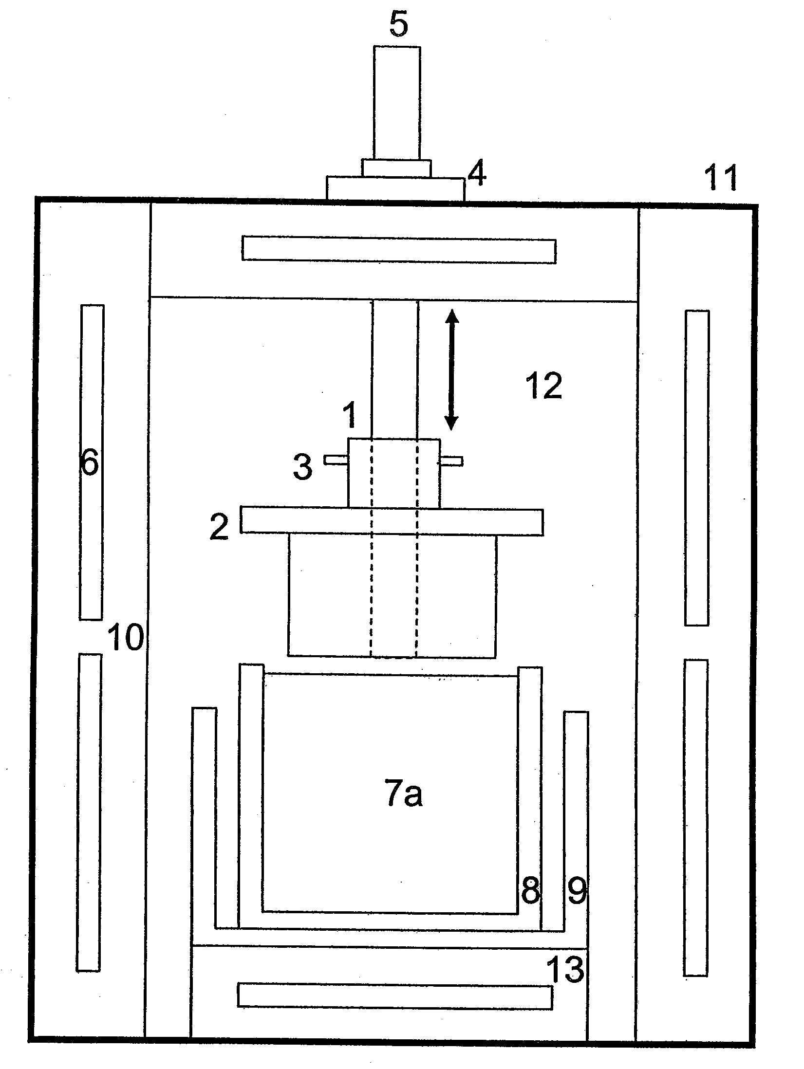
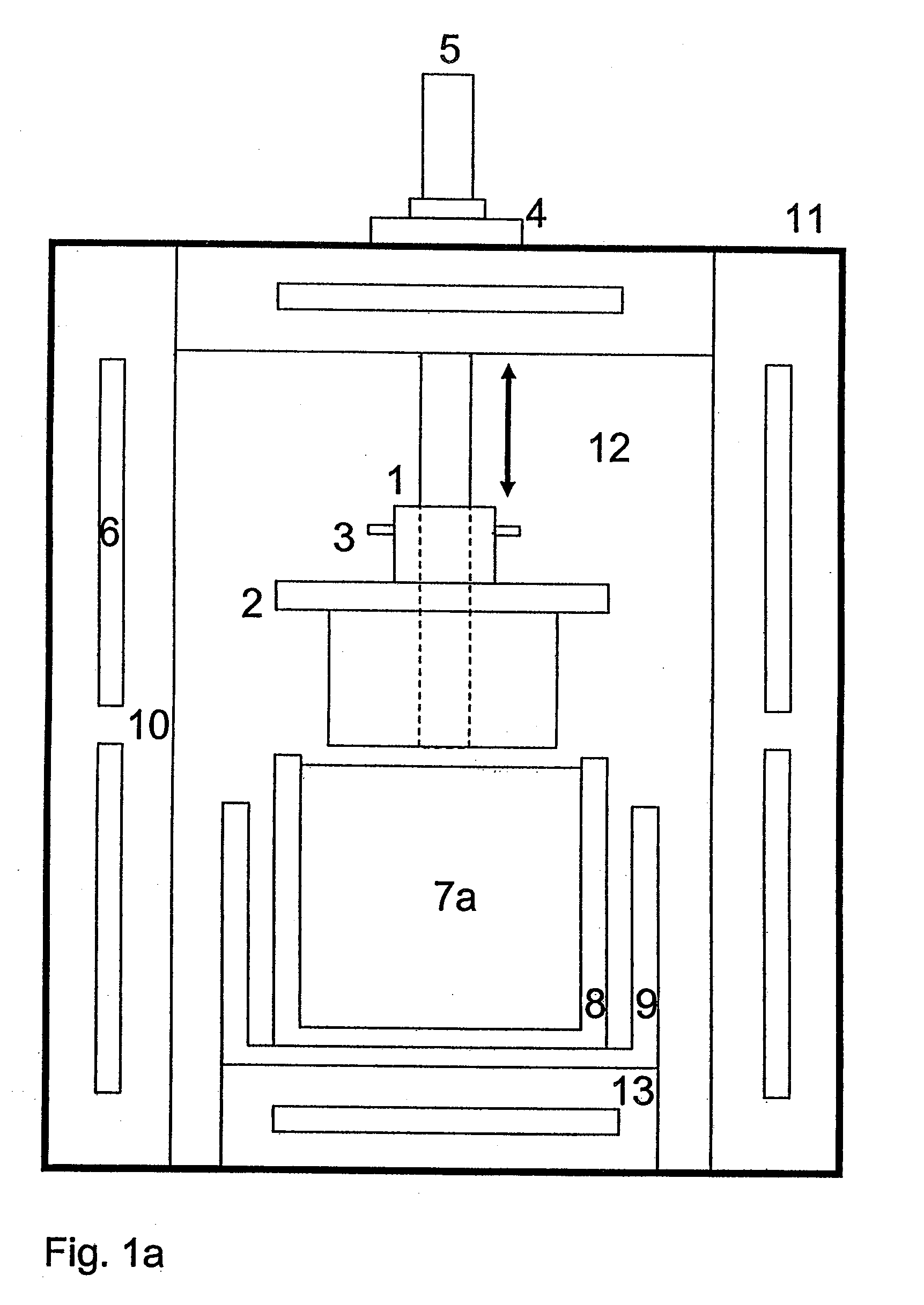
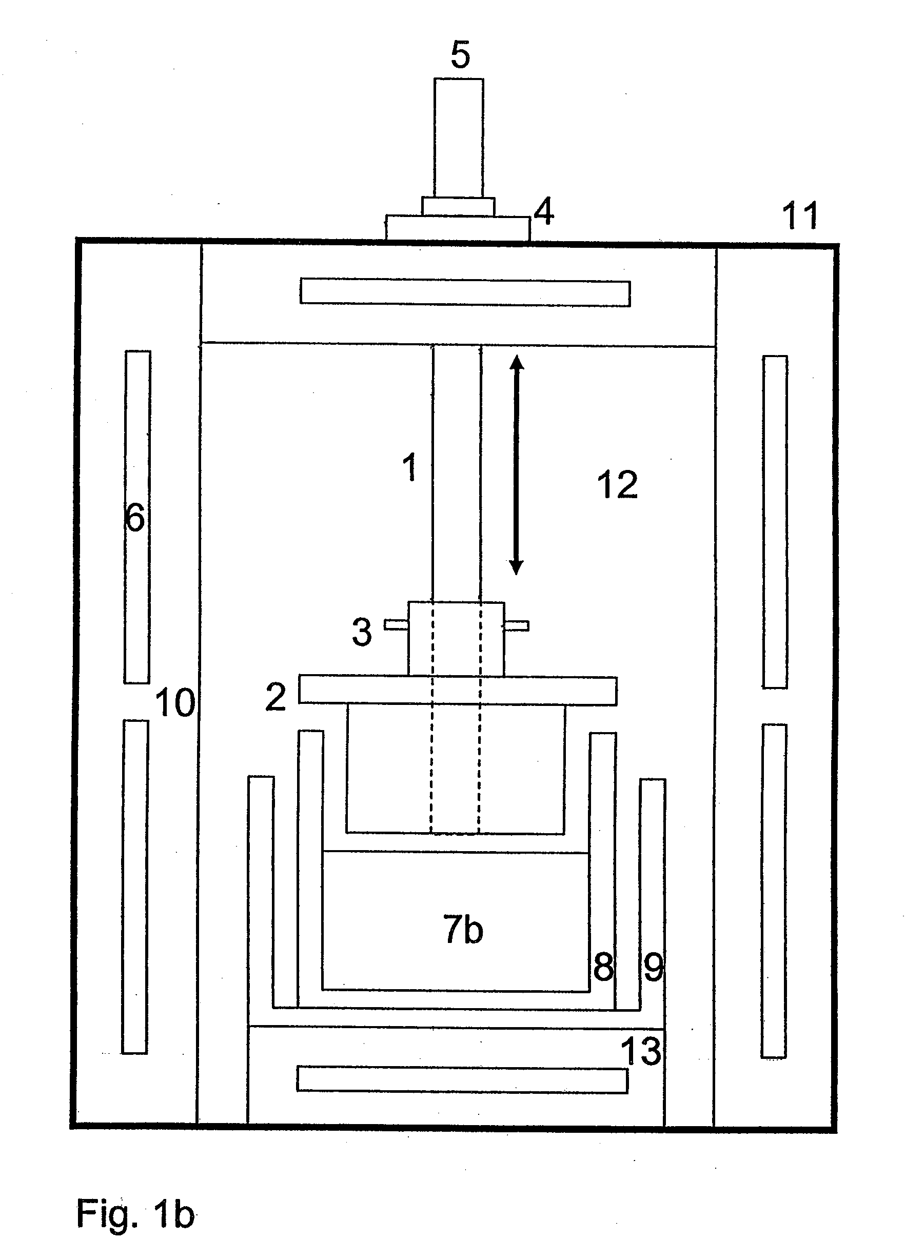
[0011]In a first alternative, the proposed device in a known manner encompasses a melting furnace with a heating chamber, in which are formed at least one supporting surface for a crucible having a lateral wall and a floor, and at least one gas purging device situated over the supporting surface and having a gas outlet facing the supporting surface. The device is characterized in that the gas outlet is formed by one or more openings in a...


PUM

PropertyMeasurementUnit
Distanceaaaaaaaaaa
Distanceaaaaaaaaaa

Abstract

The invention relates to a device and a method for producing crystalline bodies by directional solidification. The device comprises a melting furnace (11) having a heating chamber (12) in which at least one supporting surface (13) for a crucible (8) and at least one gas purging device arranged above the supporting surface (13) and having a gas outlet facing the supporting surface (13) are defined. An embodiment of the device is characterized in that the gas outlet is defined by one or more openings in a lower plunger surface of a plunger-shaped element (2) which has a geometry adapted to the inner shape of the crucible (8), said shape allowing an at least partial insertion of the plunger-shaped body (2) into the crucible (8). The gas purging device and/or the supporting surface (13) comprise an adjusting mechanism or are designed to be adjustable in such a manner that they allow an adjustment of a perpendicular distance between the supporting surface (13) and the plunger-shaped body (2). The device and the corresponding method allow carbon- and oxygen-containing materials to be discharged from the melt more efficiently and in a controlled manner. The device and the method thus allow—within certain limits—a specific adjustment of the carbon and oxygen content of the crystalline bodies.

Description

CROSS-REFERENCE TO RELATED APPLICATION[0001]This is a §371 application of International patent application number PCT / DE2008 / 000275 filed Feb. 14, 2008, which is incorporated herein by reference.TECHNICAL AREA OF APPLICATION[0002]The invention relates to a device for producing crystalline bodies by directional solidification, which encompasses a melting furnace with a heating chamber, in which are defined at least one supporting surface for a crucible and at least one gas purging device arranged over the supporting surface with a gas outlet facing the supporting surface. The invention also relates to a method for producing crystalline bodies by directional solidification using the device.[0003]Known for the massive crystal cultivation of silicon crystals in addition to cultivating monocrystalline silicon according to the Czochralksi procedure and floating zone procedure are several established methods for producing multicrystalline silicon, which all take place based on the principl...

Claims


Application Information

Patent Timeline
IPC IPC(8): B29C51/08B29C51/20
CPCC30B11/003Y10T117/10C30B29/06C30B11/006
Inventor REIMANN, CHRISTIANFRIEDRICH, JOCHENDIETRICH, MARC
Owner SOLARWORLD IND GMBH
Why Eureka
Try Eureka