Flexible low current oscillator for multiphase operations

a low-current oscillator and multi-phase technology, applied in the field of flexible oscillators, can solve the problems of large delay time with respect to each saw-tooth cycle, unsuitable, and only good relaxation oscillators

Active Publication Date: 2010-12-23
ALPHA & OMEGA SEMICON INC
View PDF1 Cites 14 Cited by
  • Summary
  • Abstract
  • Description
  • Claims
  • Application Information

AI Technical Summary

Problems solved by technology

But if switching is to be done at high frequency, the delay time becomes large with respect to each saw-tooth cycle.
Since one shot properties vary with supply voltage, the flat spot between sawtooth waves changes with supply voltage and also varies with temperature, which is not desirable.
As a result, relaxation oscillators are only good for frequencies of about 1 MHz and below.
In addition, these oscillators are not well suited for multiphase systems.
Furthermore, the conventional comparator is not cheap and the oscillator consumes a lot of current.
High current consumption is undesirable in many applications, such as portable devices.

Method used


Image

  • Flexible low current oscillator for multiphase operations
  • Flexible low current oscillator for multiphase operations
  • Flexible low current oscillator for multiphase operations

Examples


Embodiment Construction

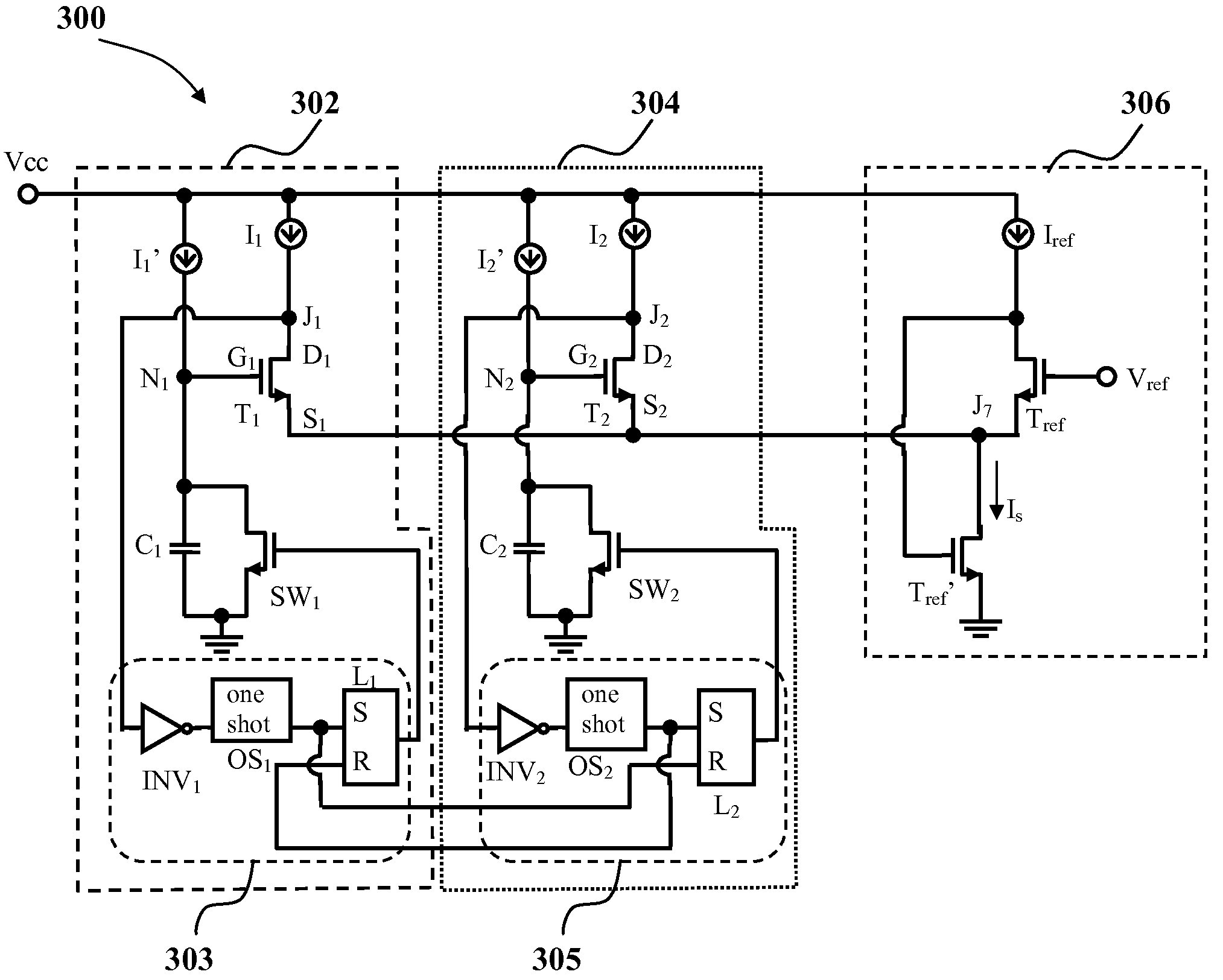
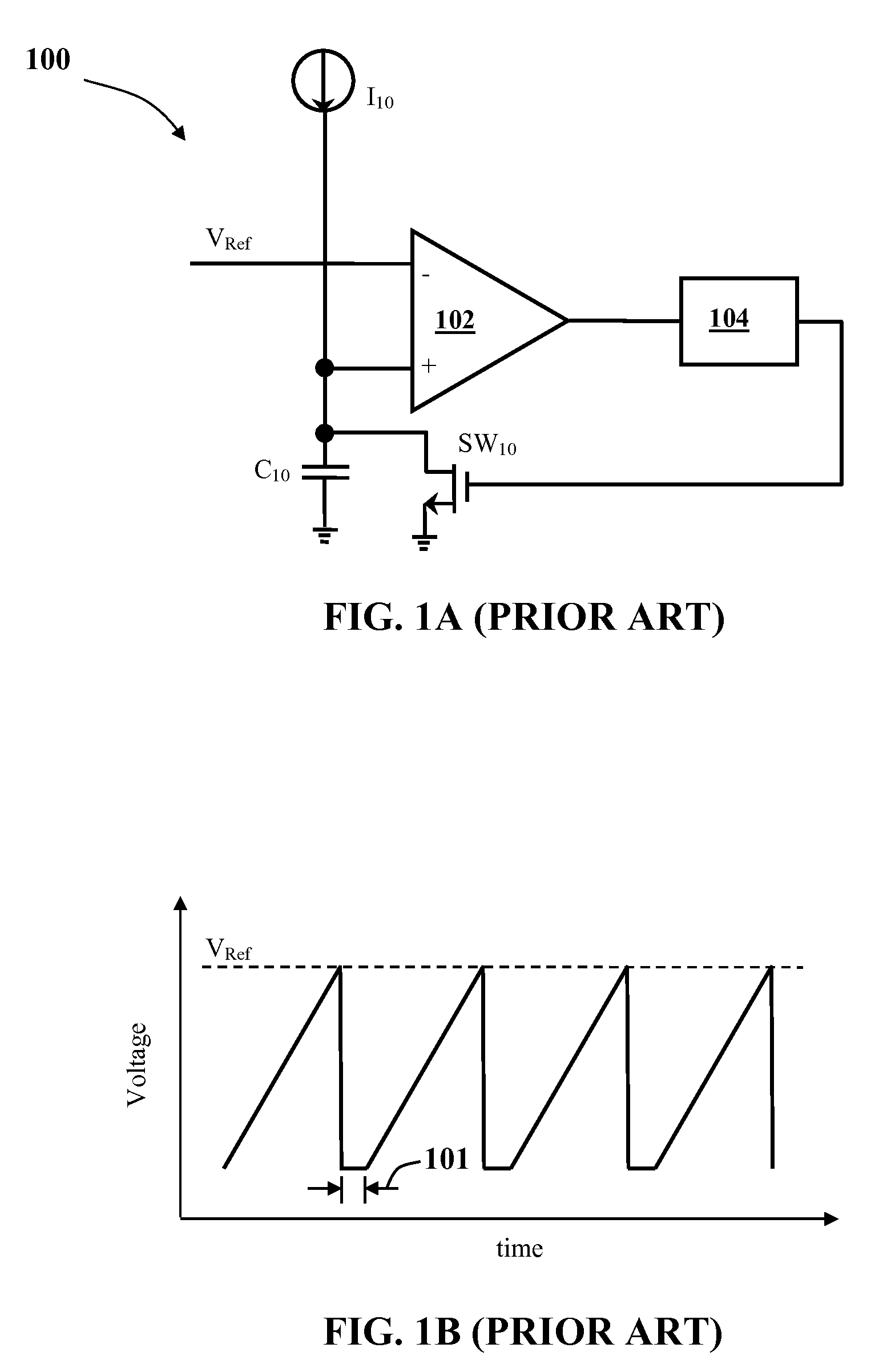
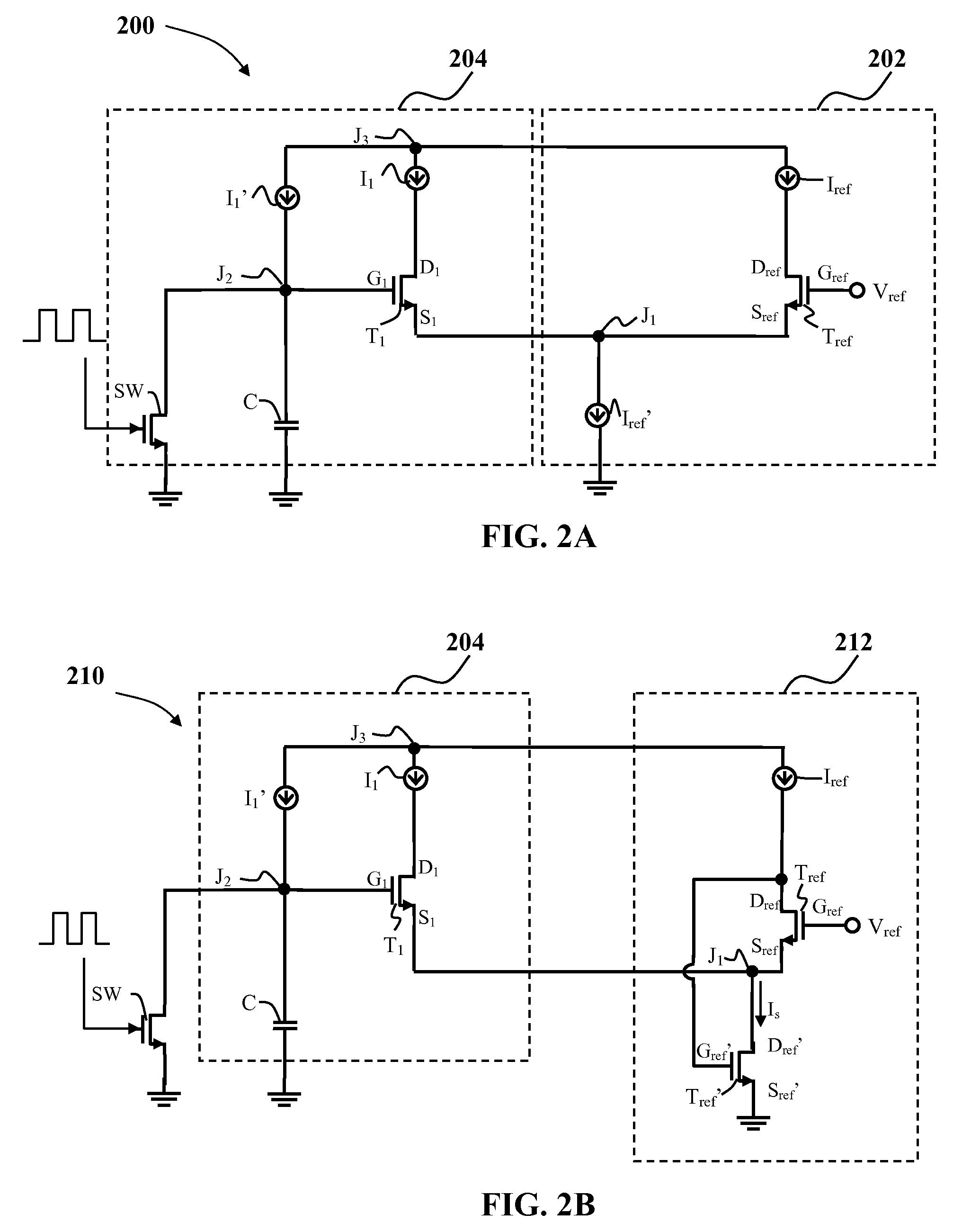
[0023]Embodiments of the present invention are directed to oscillators that overcome the disadvantages associated with prior art relaxation oscillators. Oscillator designs in accordance with embodiments of the present invention eliminate the need for a conventional comparator. The oscillator is generally comprised of one or more differential input stages that may have as many input stages as the number of phases needed with a small number of active components. Each differential stage acts as a maximum selector stage. As used herein, the term “maximum selector” refers is a circuit having multiple input stages (sometimes referred to herein as “phase stages”) that chooses the maximum voltage of the voltages of the different input stages. Selection of a given input stage by the maximum selector causes an output of the selected input stage to change. The current supplied to a given input stage may be varied as the oscillator's needs change. For example, a negative feedback loop coupled t...


PUM


Abstract

An oscillator includes a reference stage and multiple phase stages. The reference stage has a reference transistor having a gate coupled to a voltage reference and a drain coupled to a reference current source. Each phase stage includes a transistor, two current sources, a capacitor, switch, inverter, and latch. The transistor has a drain coupled to a first current source, a gate coupled to a node and a source coupled to the reference transistor's source. The capacitor and switch couple between the node and ground. The second current source couples to the node. The transistor's drain couples to the inverter's input. The inverter's output couples to the latch's set input. The latch's output couples to the switch. The inverter output also couples to the reset input of a subsequent phase stage's latch. The inverter output for a last stage couples to the reset input of a first stage latch.

Description

FIELD OF THE INVENTION[0001]This invention generally relates to an electrical circuit for generating a cyclic signal and more particularly to a flexible oscillator with low transistor count, ability to oscillate to very high frequency, and low current consumption, which can be used in multiphase operations.BACKGROUND OF THE INVENTION[0002]Within nearly every electronic subsystem is some form of waveform generator that produces cyclical waveforms. The waveform generator is oftentimes referred to as an oscillator. Depending on the application, an oscillator can be used to source regularly spaced pulses or clock signals. Oscillators are oftentimes rated depending on their stability and accuracy, frequency adjustability (i.e., tunability), gain of active circuit, start-up time, power consumption, etc.[0003]A type of oscillator commonly known as a relaxation oscillator is the most commonly used architecture for lower frequency oscillator designs. FIG. 1A is an electrical schematic diagra...

Claims


Application Information

Patent Timeline
Patent Type & Authority Applications(United States)
IPC IPC(8): H03B27/00
CPCH03K3/354H03K4/502
Inventor MOHTASHEMI, BEHZAD
Owner ALPHA & OMEGA SEMICON INC
Why Eureka
Try Eureka