Multilayer Capacitor

a multi-layer capacitor and capacitor technology, applied in the field of multi-layer capacitors, can solve the problems of increasing the esl level, the inability of the decoupling circuit to divert an alternating current component of the power source current, and the inability to reduce the circuitry size of the decoupling circuit, so as to reduce the amount of increase, increase the resistive component, and increase the esr

Active Publication Date: 2010-12-23
KYOCERA CORP
View PDF3 Cites 20 Cited by
  • Summary
  • Abstract
  • Description
  • Claims
  • Application Information

AI Technical Summary

Benefits of technology

[0017]According to the invention, in the presence of the first internal relay electrode disposed between the first internal capacitor electrode and the first external terminal electrode, and the second internal relay electrode disposed between the second internal capacitor electrode and the second external terminal electrode, the electric current path within the multilayer capacitor can be made longer and the ESR of the multilayer capacitor is thus significantly increased. When it is desired to reduce the amount of increase in the ESR, the numbers of, respectively, the first internal relay electrode and the second internal relay electrode are increased to increase resistive components in parallel. Although the first internal relay electrode and the second internal relay electrode each have an inductance, since they are arranged so as to be opposed to each other with the dielectric layer interposed therebetween, the inductance of the first internal relay electrode and the inductance of the second internal relay electrode cancel each other out. This makes it possible to keep the level of ESL low in the multilayer capacitor. In this way, according to the multilayer capacitor embodying the invention, ESR control can be exercised properly while maintaining the level of ESL low.
[0018]Moreover, the first external terminal electrode and the second external terminal electrode are formed on both of the upper surface and the lower surface of the multilayer body. That is, any one of the upper surface and the lower surface of the multilayer body can be used as a mounting surface which is opposed to a circuit board. This makes it possible to permit easing of constraints in terms of a direction in which the multilayer capacitor is mounted on the circuit board. Further, the multilayer body is constructed by stacking a plurality of rectangular dielectric layers on top of one another in the stacking direction. In this construction, the distance between the mounting surface, namely the upper surface as well as the lower surface, and the center of gravity of the multilayer body is shorter than the distance between the left-hand surface, as well as the right-hand surface, and the center of gravity of the multilayer body. This results in the advantage that the multilayer capacitor is hardly caused to topple over when mounted on the circuit board.

Problems solved by technology

A reduction in the circuitry size of the decoupling circuit cannot be achieved without reducing the number of constituent capacitors.
Therefore, depending upon frequency, there arises the problem that the decoupling circuit is incapable of diverting an alternating current component of power source current.
However, if the level of ESR is raised simply by lengthening the electric current path, there will arise the problem that the level of ESL is also raised.
However, even if this method is adopted, the problem of high ESL level still exists.

Method used


Image

  • Multilayer Capacitor
  • Multilayer Capacitor
  • Multilayer Capacitor

Examples


examples

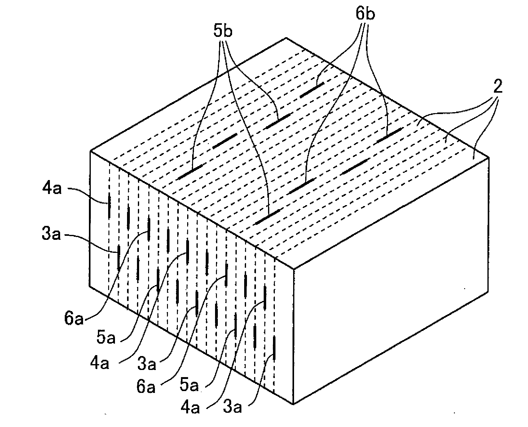
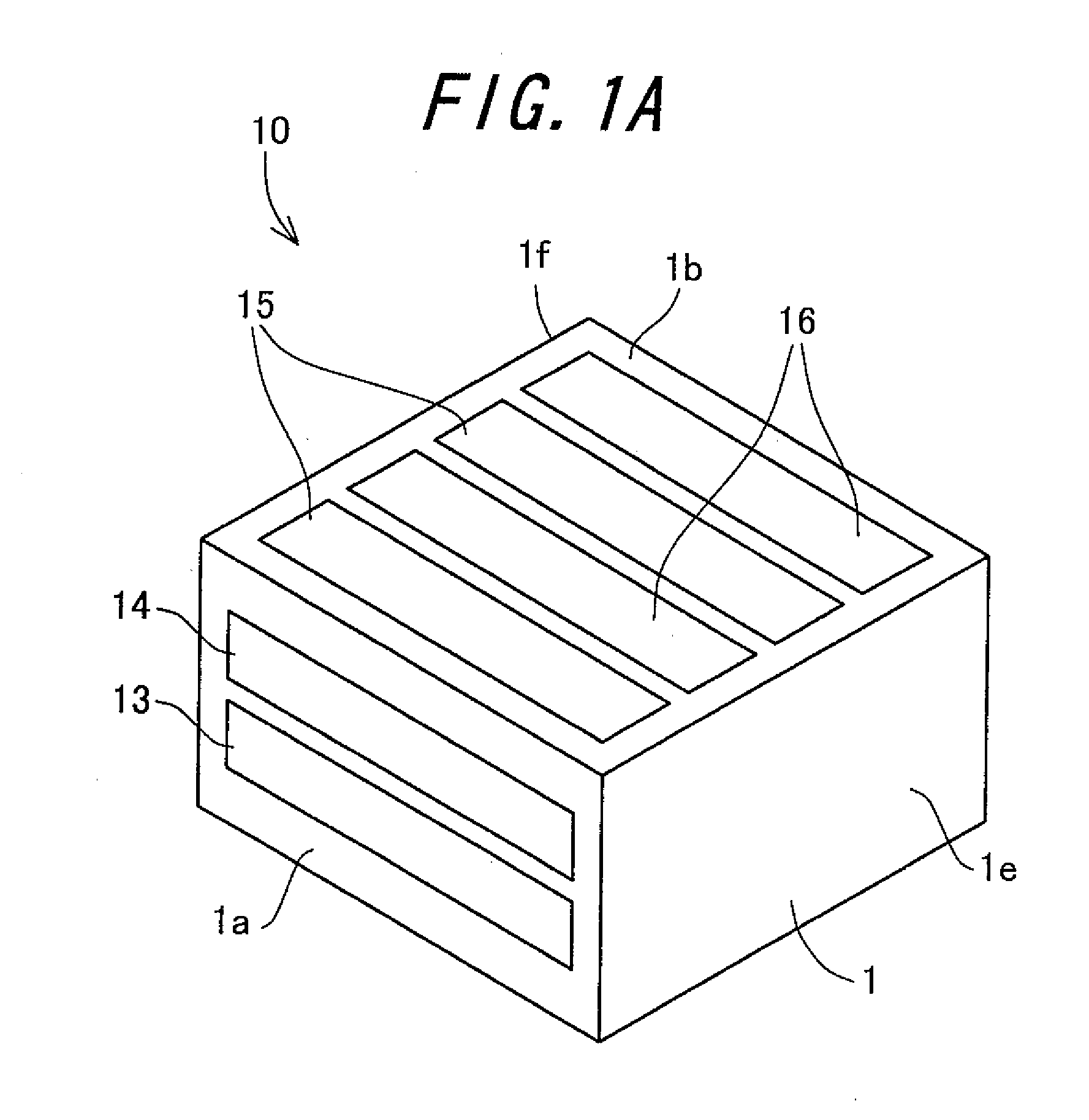
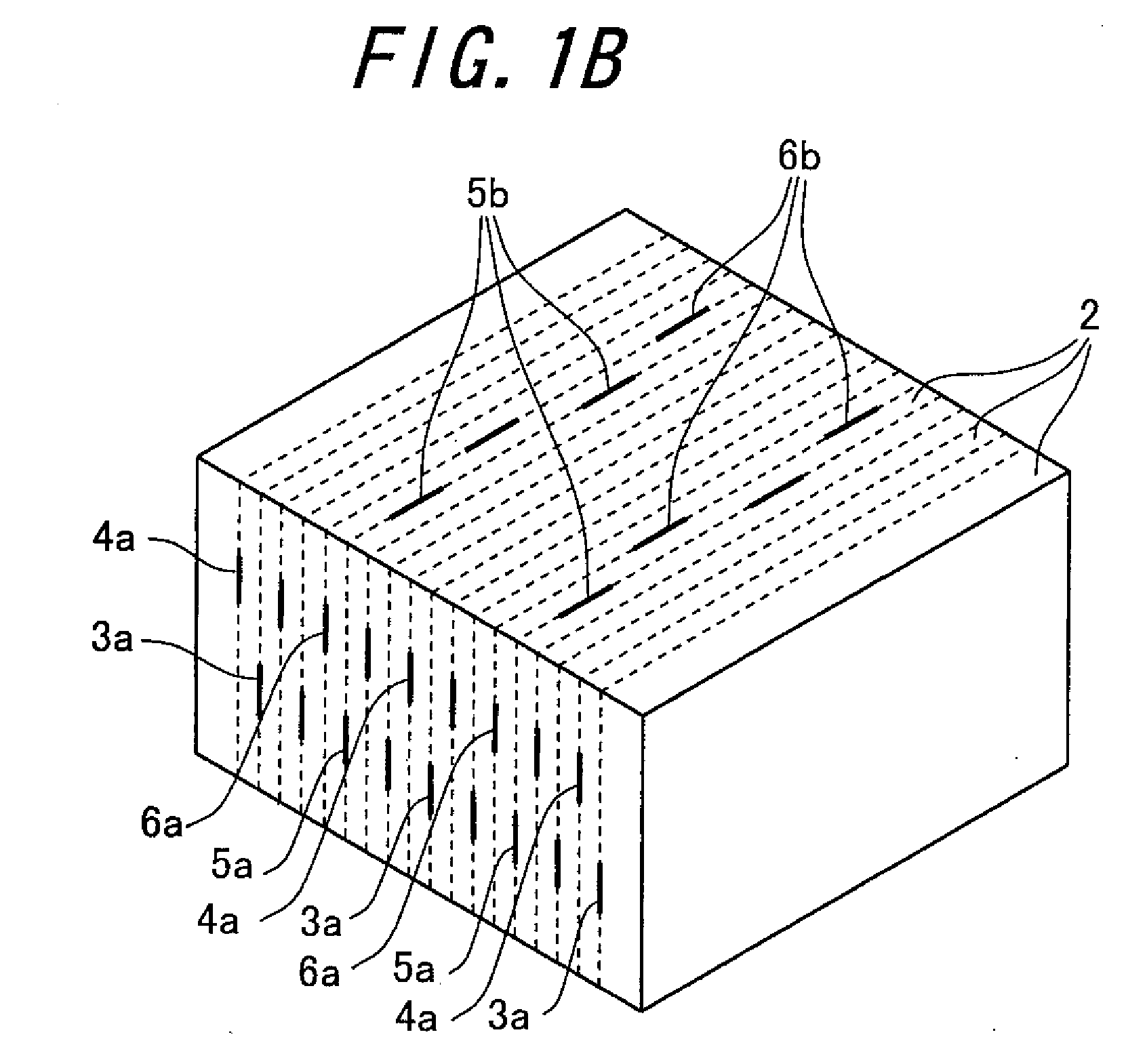
[0065]A test sample 1 having the following structure was fabricated by way of the multilayer capacitor 10 according to the invention.

[0066]The multilayer body 1 is produced in the form of a dielectric block of rectangular parallelepiped shape constructed by stacking together rectangular dielectric layers 2, each of which is 0.8 mm long and 1.6 mm wide, in the stacking direction so that the dimension of the dielectric block in the stacking direction is 1.6 mm. The material used for the dielectric layer 2 is ferroelectric ceramics predominantly composed of barium titanate. The first internal capacitor electrode 3 and the second internal capacitor electrode 4, which are each formed by using a conductor material predominantly composed of nickel and 100 in number, are arranged in an alternating manner within the multilayer body 1. The first internal relay electrode 5 and the second internal relay electrode 6, which are each formed by using a conductor material predominantly composed of n...


PUM


Abstract

The invention relates to a multilayer capacitor capable of controlling ESR while maintaining the level of ESL low. A multilayer capacitor (10) includes a plurality of first and second internal capacitor electrodes (3, 4) which are formed inside a multilayer body (1) of rectangular parallelepiped shape constructed by stacking a plurality of rectangular dielectric layers (2) on top of one another in a stacking direction; first and second external relay electrodes (13, 14) which are disposed on left-hand and right-hand surfaces of the multilayer body (1); first and second internal relay electrodes (5, 6) which are disposed inside the multilayer body (1) and arranged so as to be opposed to each other with the dielectric layer (2) interposed therebetween; and first and second external terminal electrodes (15, 16) which are disposed on upper and lower surfaces of the multilayer body (1).

Description

TECHNICAL FIELD[0001]The present invention relates to a multilayer capacitor that is suitable for use in a decoupling circuit or the like for stabilizing power supply current which is supplied to a power terminal of an IC.BACKGROUND ART[0002]Heretofore, it has been customary to connect a decoupling circuit between an IC and a power source in parallel relation to the IC so that, out of power source current, an alternating current component is diverted by the decoupling circuit to supply only a direct current component to the IC. Such a function of the decoupling circuit can be attained by decreasing the impedance of the decoupling circuit below a predetermined value over a wide band of frequencies ranging from low frequencies to high frequencies. In general, the decoupling circuit is composed of a plurality of capacitors. Since the capacitor has, in addition to an electrostatic capacitance, an equivalent series inductance (hereafter referred to as “ESL”), it follows that the impedanc...

Claims


Application Information

Patent Timeline
Patent Type & Authority Applications(United States)
IPC IPC(8): H01G4/005
CPCH01G4/012H01G4/30H01G4/232
Inventor OSAWA, SHINICHI
Owner KYOCERA CORP
Why Eureka
Try Eureka