
Desulfurizing system for a fuel cell power plant

a technology of desulfurizing system and fuel cell power plant, which is applied in the direction of hydrogen separation using solid contact, electrochemical generators, chemistry apparatus and processes, etc., can solve the problems of significant waste of sulfur from fuel, and the requirements of the power plant may not afford a shut-down period suitable for regeneration of the sulfur removal bed

Inactive Publication Date: 2010-12-23
VANDERSPURT THOMAS H +4
View PDF4 Cites 3 Cited by
  • Summary
  • Abstract
  • Description
  • Claims
  • Application Information

AI Technical Summary

Benefits of technology

The patent describes a system for removing sulfur from fuel used in a fuel cell power plant. The system includes a sulfur removal bed made of manganese oxide that removes sulfur from the fuel as it passes through the bed. The sulfur is then stored in a sulfur capture bed made of nickel oxysulfide catalyst. The sulfur capture bed is heated to convert the sulfur back to gas, which is then stored in a container. The system can be regenerated by heating the bed and passing a steam and oxygen containing gas through it. The technical effect of the system is to efficiently and safely remove sulfur from the fuel and store it, reducing the risk of sulfur release into the environment.

Problems solved by technology

However, for solid oxide electrolyte fuel cell (“SOFC”) power plants that operate at extremely high temperatures, as well as for proton exchange membrane electrolyte fuel cell (“PEM”) power plants operating on a high temperature reformate fuel stream, efficient removal of sulfur from fuel remains a significant problem.
In an additional embodiment, requirements of the power plant may not afford a shut-down period suitable for regeneration of the sulfur removal bed.
However, galaxite is preferred because it limits the conversion of manganese oxide to other less reactive minerals on repeated cycles of sulfide capture and regeneration.

Method used


Image

  • Desulfurizing system for a fuel cell power plant
  • Desulfurizing system for a fuel cell power plant

Examples


Embodiment Construction

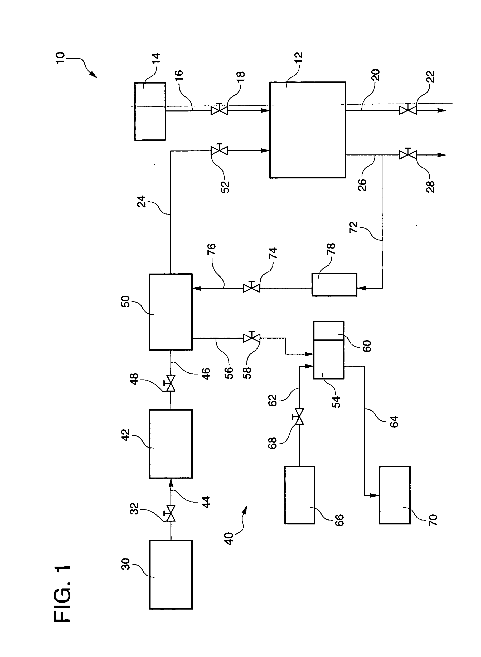
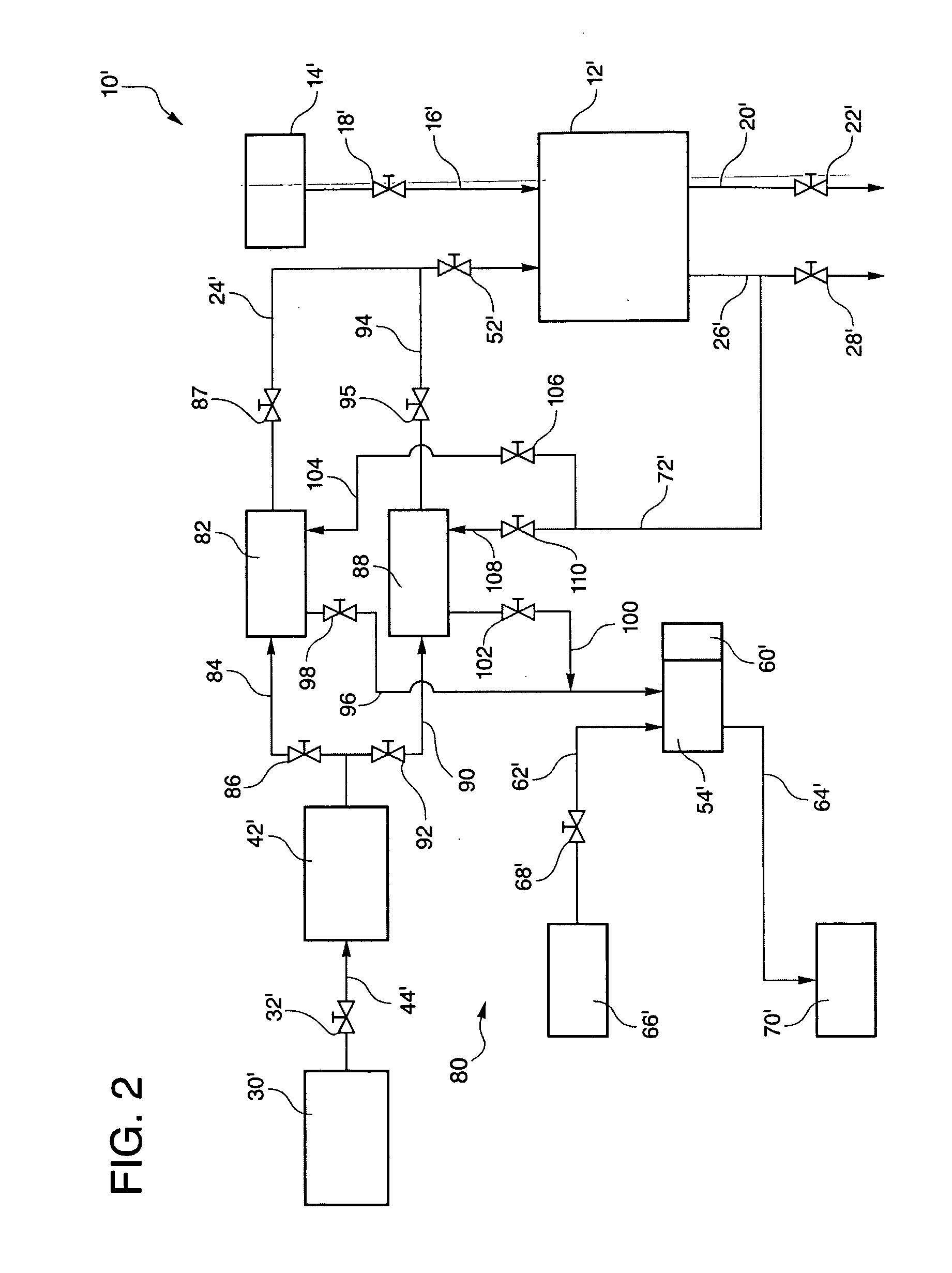
[0015]Referring to the drawings in detail, a desulfurizing system for a fuel cell power plant is shown in FIG. 1. The fuel cell power plant is generally designated by the reference numeral 10. The power plant 10 includes at least one fuel cell 12 as part of the fuel cell power plant 10. An oxidant supply source 14 directs flow of an oxygen rich oxidant reactant stream through an oxidant inlet line 16 and oxidant inlet valve 18 into the fuel cell 12, and unused oxidant passes out of the fuel cell 12 through an oxidant exhaust line 20 and oxidant exhaust valve 22. A fuel inlet line 24 directs a gaseous, hydrogen-rich reformate fuel stream into the fuel cell 12, and unused fuel passes out of the fuel cell 12 through a fuel exhaust line 26 and fuel exhaust valve 28. The fuel cell 12 is configured to produce electricity as the fuel and oxidant reactant streams flow through the fuel cell 12. The fuel cell power plant 10 also includes a fuel source 30 for storing a sulfur-containing fuel, ...


PUM

PropertyMeasurementUnit
temperatureaaaaaaaaaa
electrical currentaaaaaaaaaa

Abstract

The system (40) provides for directing a hydrogen-rich reformate fuel stream from a reformer (42) through a sulfur removal bed (50) having a sulfur removal material consisting of manganese oxide secured to a support material. A regeneration fluid is intermittently directed through the bed (50) to remove sulfur and regenerate the bed. A regeneration-produced sulfur containing stream is then directed into a sulfur capture bed (54) having a heat source (60) and a flush inlet (62) and flush outlet (64). The sulfur capture bed (54) includes sulfur capture material consisting of nickel oxysulfide catalyst supported on silicon carbide. When the heat source (60) heats the sulfur capture bed (54) a flush liquid passed through the flush inlet (62), capture bed (54), and flush outlet (64) to transport elemental sulfur to a sulfur storage container (50).

Description

TECHNICAL FIELD[0001]The present disclosure relates to fuel cells that are suited for usage in transportation vehicles, portable power plants, or as stationary power plants, and the disclosure especially relates to an improved system for removing sulfur from a fuel for a fuel cell power plant.BACKGROUND ART[0002]Fuel cells are well known and are commonly used to produce electrical current from hydrogen containing reducing fluid fuel and oxygen containing oxidant reactant streams to power electrical apparatus or to serve as electricity generators. As is well known in the art, a plurality of fuel cells are typically stacked together to form a fuel cell stack assembly which is combined with controllers and other components to form a fuel cell power plant.[0003]In fuel cells of the prior art, it is well known that utilization of auto-thermal reformers and / or partial oxidation catalytic reformers enables traditional hydrocarbon fuels, such as gasoline, diesel fuel, distillate fuels, natu...

Claims


Application Information

Patent Timeline
Patent Type & Authority Applications(United States)
IPC IPC(8): H01M8/06
CPCC01B3/56C01B2203/0233C01B2203/0244C01B2203/0261C01B2203/042C01B2203/043Y02E60/525C01B2203/066H01M8/0675H01M2008/1095H01M2008/1293Y02E60/50C01B2203/0485
Inventor VANDERSPURT, THOMAS H.DARDAS, ZISSISTANG, XIANEWMAN, CAROLINE A.SHE, YING
Owner VANDERSPURT THOMAS H
Learn More