
Disconnection detecting device

a detection device and disconnection technology, applied in the direction of battery/fuel cell control arrangement, instruments, transportation and packaging, etc., can solve the problems of reducing the power and fuel consumption of the engine of the practical vehicle, unable to detect the occurrence of disconnection, and reducing the available battery capacity

Active Publication Date: 2010-12-30
YAZAKI CORP
View PDF6 Cites 26 Cited by
  • Summary
  • Abstract
  • Description
  • Claims
  • Application Information

AI Technical Summary

Benefits of technology

[0018]Accordingly, an object of the present invention is to provide a disconnection detecting device that is capable of effectively detecting a disconnection with inexpensive circuit configuration, in which a source voltage supplied to the voltage detection unit does not vary to a large extent in a disconnection or in a normal state.
[0027]The disconnection detection unit with the above preferable configuration is capable of accurately detecting the disconnection.
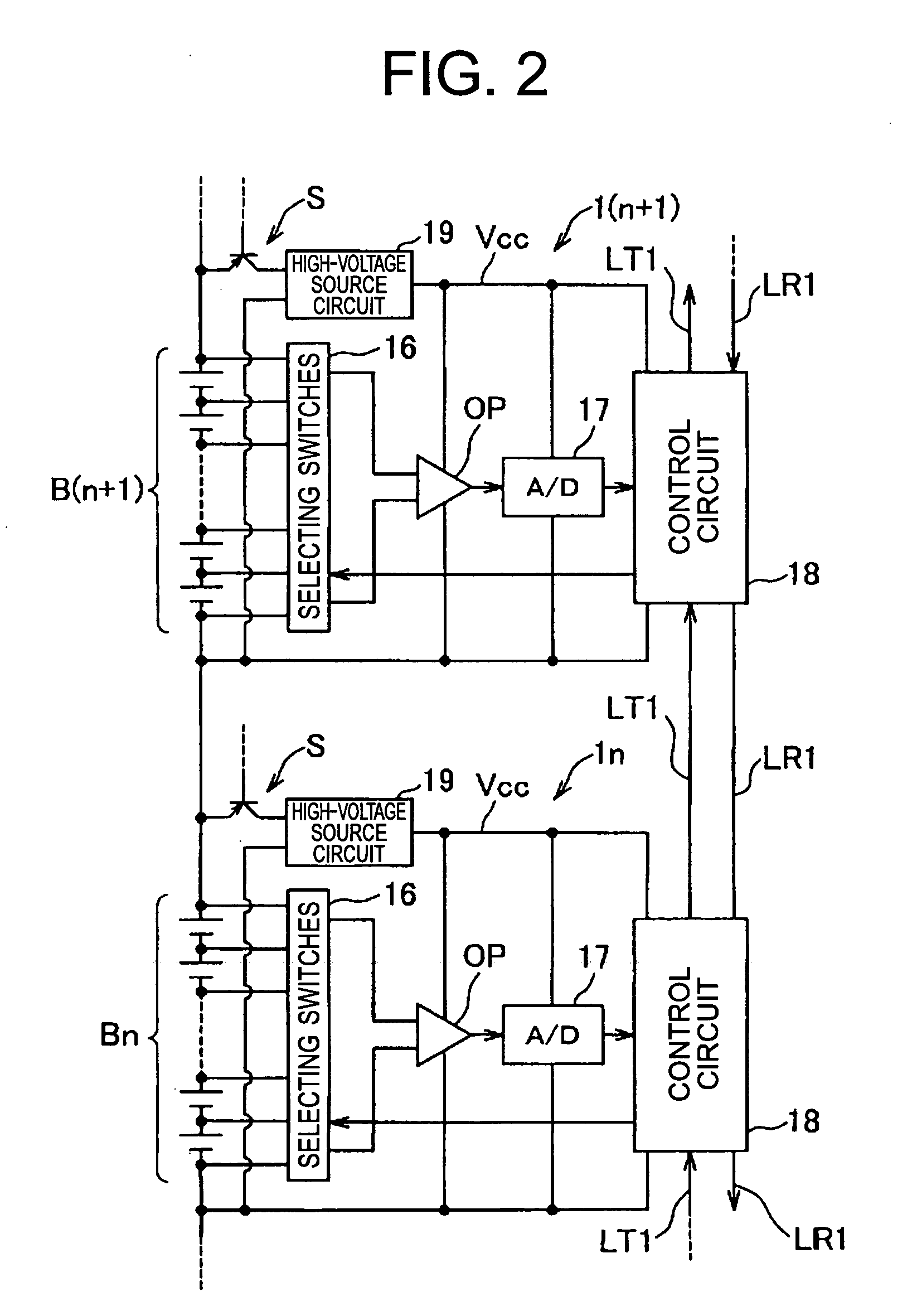
[0029]By virtue of voltage clamping by the first diode and the second diode, the disconnection detecting device with the above preferable configuration is capable of preventing an abnormal state from occurring in the voltage detection unit even when the switch element is turned on, for voltage clamping of the first and second diodes prevents the electric potential of the ground terminal of the voltage detection unit dedicated to the higher-ordered battery block and the electric potential of the power supply terminal of the voltage detection unit dedicated to the lower-ordered battery block from becoming unbecomingly large.

Problems solved by technology

Accordingly, existence of variation in the SOCs depending on the unit cells practically results in decrease in available battery capacity.
In a case of the HEV, this further causes insufficient assist / regeneration functionality for supplying complementary battery energy to the engine when the automobile climbs a slope or regenerating energy for the battery when the automobile goes downhill, which may result in decrease in practical vehicle's engine power and fuel consumption.
When this intermediate electric potential is resulted, it is not possible to successfully detect occurrence of the disconnection, for the voltages between both ends, detected by the voltage-detection integrated circuit IC, of the lowest-ordered unit cell of the higher-ordered battery block and the highest-ordered unit cell of the lower-ordered battery block are substantially the same as in a normal state.
It is not possible to discern whether occurrence of such shifting has been caused by an abnormal state of the unit cell or by a disconnection.
However, when the charging time is short, the voltage cannot be correctly measured.
As has been discussed in the foregoing, when the cell voltage measuring device has the voltage-detection integrated circuit IC powered by the unit cell, the connected resistance is so large that it is difficult to supply power when a disconnection occurs.
Also, cost increases when the power is supplied from the low-voltage battery using the DC / DC converter.
Further, such conventional device are effective in a case where variation in voltage among the battery blocks is small (with 10 percent maximum specified), but it will erroneously detect occurrence of disconnection due to the large variation in voltage among the battery blocks (for example, see Japanese Patent No. 3300309).

Method used


Image

  • Disconnection detecting device
  • Disconnection detecting device
  • Disconnection detecting device

Examples


Embodiment Construction

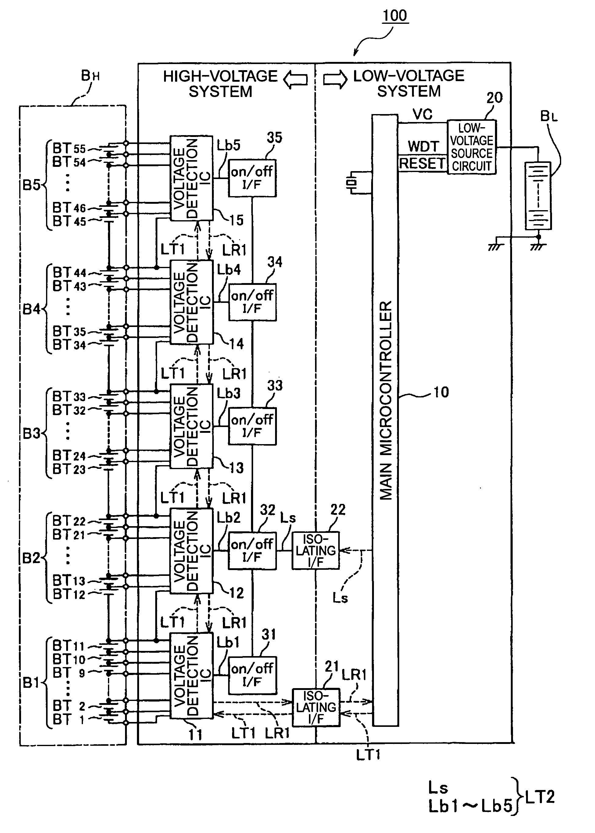
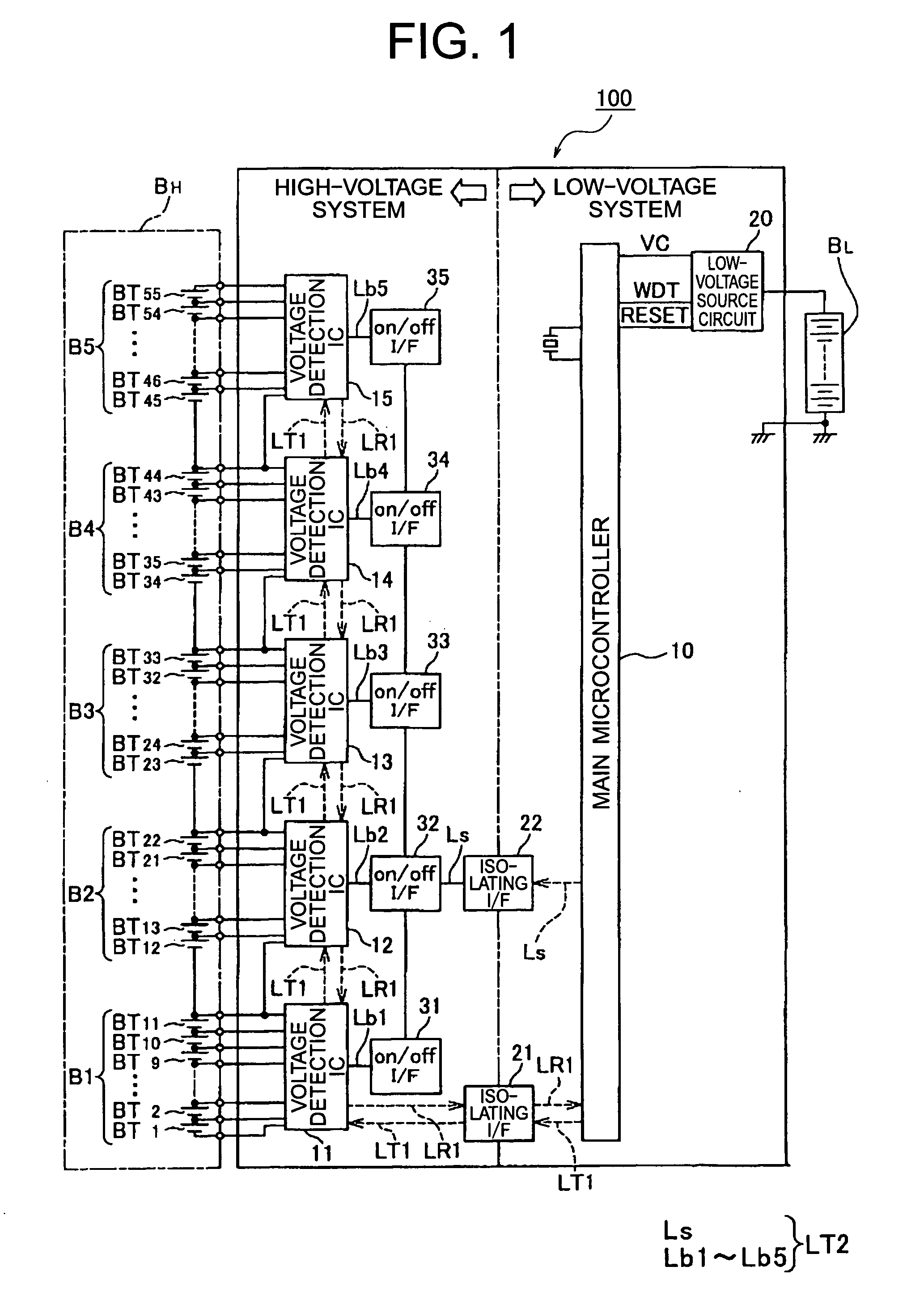
[0038]The following describes a voltage detecting device according to an embodiment of the present invention with reference to the attached drawings. The voltage detecting device of this embodiment is intended for but not limited to in-vehicle installation and application.

[0039]Referring to FIG. 1, there is shown a low-voltage battery BL that includes secondary cells. The low-voltage battery BL serves as a power source for driving a starter that starts an engine. Although not shown, an alternator may be connected to both ends of the low-voltage battery BL as a charger.

[0040]In the same figure, there is shown a high-voltage battery BH that serves as a power source for an electric motor in a hybrid electric vehicle (HEV) that is driven by an internal combustion engine and the electric motor. Although not shown, an engine as a load and an alternator as a charger may be connected to both ends of the high-voltage battery BH.

[0041]The high-voltage battery BH may be divided into five batte...


PUM


Abstract

A switch element is configured to decrease an impedance of a voltage-detection integrated circuit that detect voltage between both ends of unit cells of a higher-ordered battery block, for adjacently-connected pair of the higher-ordered battery block and a lower-ordered battery block. The voltage-detection integrated circuit is configured to detect disconnection of an electrical wire when voltage between both ends of a lowest-ordered unit cell that is detected with the switch element turned on is equal to or lower than a threshold.

Description

CROSS REFERENCE TO RELATED APPLICATION[0001]The priority application Japan Patent Application No. 2009-151064 upon which this patent application is based is hereby incorporated by reference.BACKGROUND OF THE INVENTION[0002]1. Field of the Invention[0003]The present invention generally relates to a disconnection detecting device, and in particular to a disconnection detecting device for a battery including battery blocks each constituted by mutually-series-connected unit cells, the device being configured to detect a disconnection of an electrical wire connecting a connection point connecting, the device configured to detect disconnection of an electrical wire connected between adjacently-connected pair of higher-ordered battery block and lower-ordered battery block to a ground terminal of a voltage detection unit configured to detect a voltage between both ends of a unit cell belonging to the higher-ordered battery block and a power supply terminal of a voltage detection unit config...

Claims


Application Information

Patent Timeline
Patent Type & Authority Applications(United States)
IPC IPC(8): G01R31/02G01R31/58
CPCB60L11/14B60L11/1861B60L11/1868G01R31/026G01R31/3658Y02T10/70Y02T10/7005Y02T10/7044Y02T10/7055Y02T10/7066Y02T10/7077H02J7/0021G01R31/396B60L50/16B60L58/12B60L58/20G01R31/54G01R31/52Y02T10/7072G01R31/58H02J7/0013H02J7/0048
Inventor ISHIKAWA, SATOSHIMATSUURA, KIMIHIRO
Owner YAZAKI CORP
Learn More